Donkey Kong Scratch Build
October 2016
So earlier this year I decided to do a Restoration/Scratch Build of an original US Donkey Kong cabinet. This is probably more a Scratch Build rather than Restoration but I am going to go to a concerted effort to build this with as much original hardware as possible and also construct the cabinet to be as close to spec to the original cabinets dimensions as well. Most of the hardware has been sourced from the US with a mixture of it being original parts from a parted out DK cab and/or reproduction parts from Mike's Arcade.
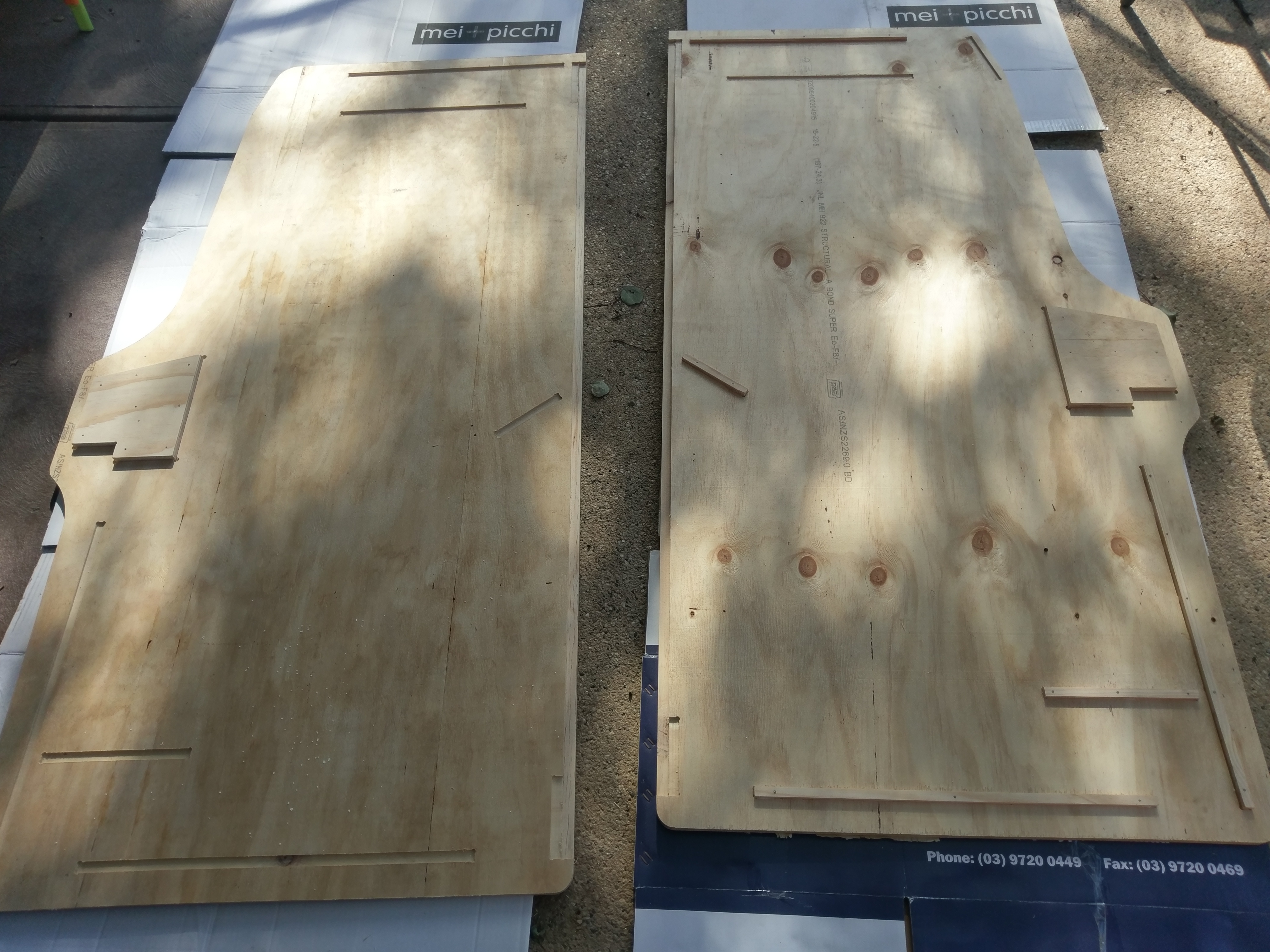
The cabinet itself will be made from a 15mm CD grade plywood. I decided just to use a decent construction grade ply mainly because of cost as furniture grade was nearly triple the cost. Additionally, since this is going to get painted, any imperfections could be filled in and sanded before final coats of the paint would be applied, reducing the need for that higher quality finish on the timber surface. At the time of writing this I am almost done with the painting and in hindsight I might have opted to use at least one sheet of black Melamine as there are a number of parts which needed to be painted black and it would have been a lot easier if that had already been taken care of for me. However I still would have had to paint the insides of the main side panels as the outside of those needed to be painted with the DK Blue so raw Plywood would have had to be used anyway. I think you could easily get away with x2 sheets of the plain CD Grade Ply to cover the main sides and potentially 1 sheet of black melamine for the rest of the internal parts that needed to be painted black. Anyway, the original cabs were all painted so I guess this approach is more authentic.
I sourced my cabinet plans from www.classicarcadecabinets.com. Brian is quite active on the KLOV community and has done a fantastic job putting this “free” resource together for the wider arcade community. I took the plans to a local CNC guy and after converting them to metric and configuring the tool paths for cutting, they were able to produce all of the cabinet parts for me. Some notes so far on this process and the plans:
- Not all of his plans are guaranteed to be 100% accurate. These particular ones for DK however have been re-cut and verified against an original cabinet so are as close to the original as you can get.
- There is no back door in these plans. I am going to work with him to get the plans updated to include these. Luckily I have an original cabinet for comparison.
- Not all of the parts for the coin box seem to be present so I need to work out that later. (04/10 Update: I have assembled the coin box housing, it was missing the back piece which I had to add myself. Also there are no plans for the coin box itself so will have to look at the original and re-create it… or just make something up :) )
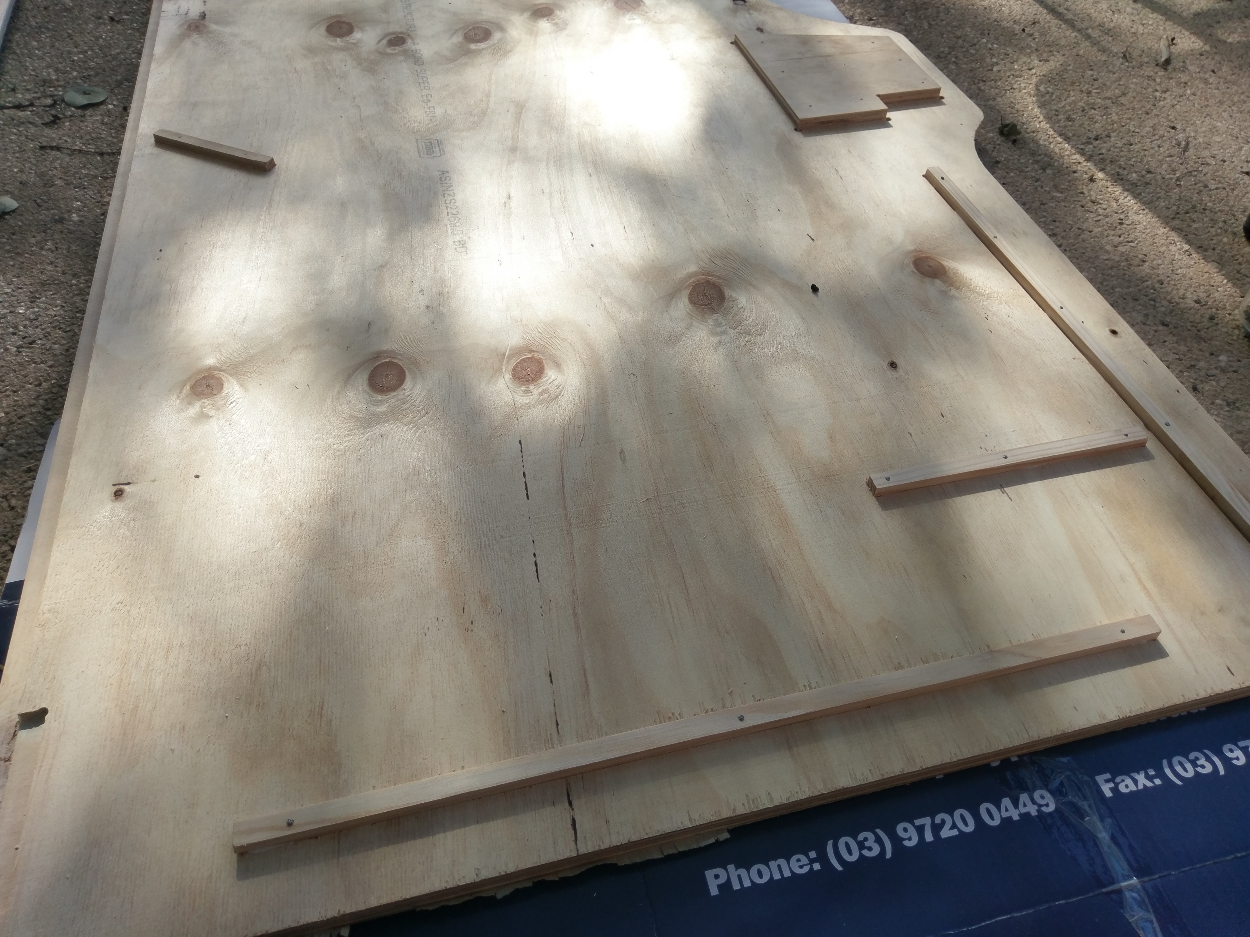
- Even though the plans include the small blocking pieces which are to be used on the inside of the main sides, these are quite fiddly and messy to get cut on most CNC's so I decided to get some sticks of 12mm x 12mm dowel from Bunnings which did the trick.
- The other thing is that this cabinet build assumes you are going to use an original Sanyo20EZ monitor and chassis which comes with its own frame and is mounted in these cabs with some specific brackets. Whilst I have the brackets I do not have an original monitor so will just be looking to fit a standard 19” CRT and because of this I will need to make my own bracket and support for this.. This will come later.
Cabinet Prep:
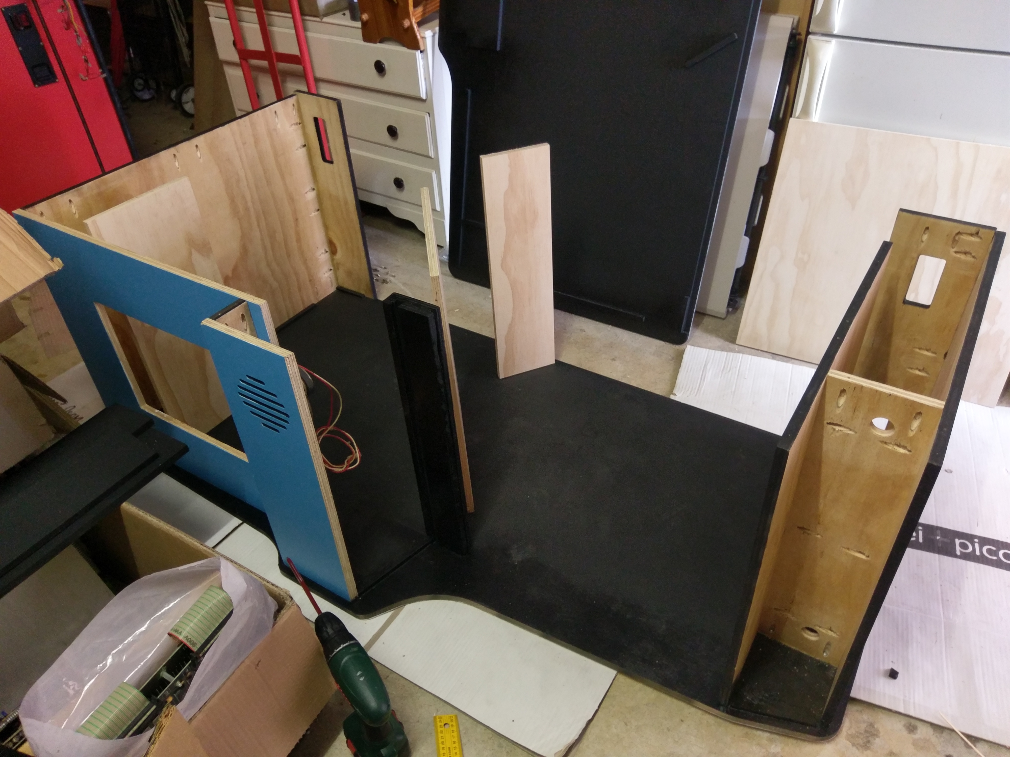
After getting all of the parts home from the CNC workshop the first thing I did was fit all of the blocking pieces to the inside of each of the main side panels.
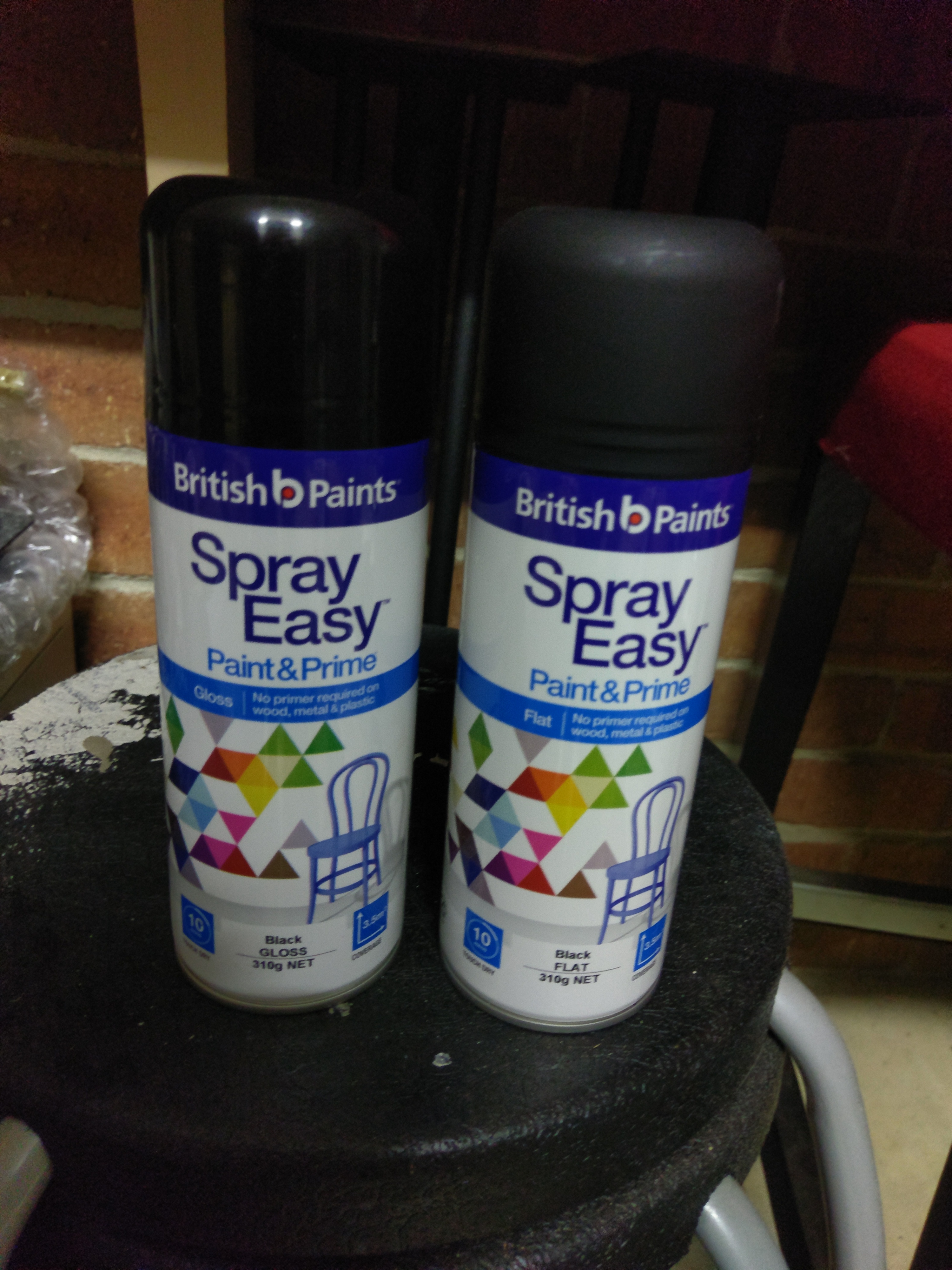
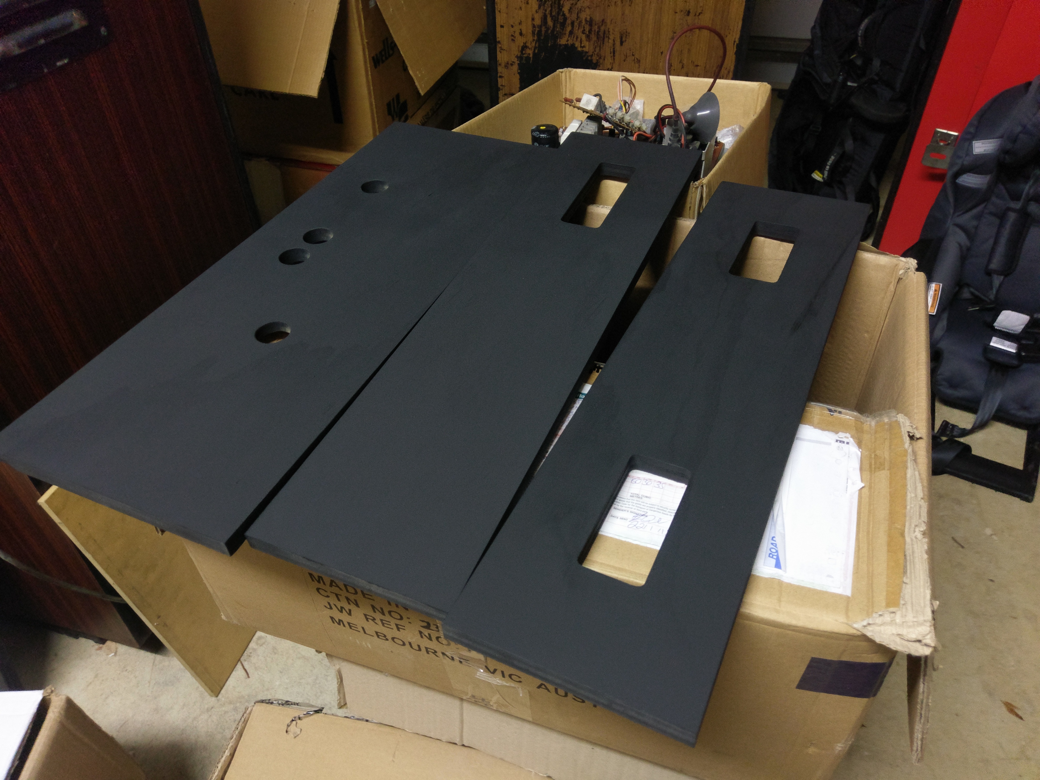
I then applied a couple of coats of Flat Black Spray Paint to the inside of these panels. After letting that dry and also applying the same paint to other parts that will be visible to the user (top of the control panel and the lower marquee support) I decided to get some Black Gloss and apply that to the front inside edge of these panels as the gloss finish is more aesthetically pleasing and durable than just the flat black.
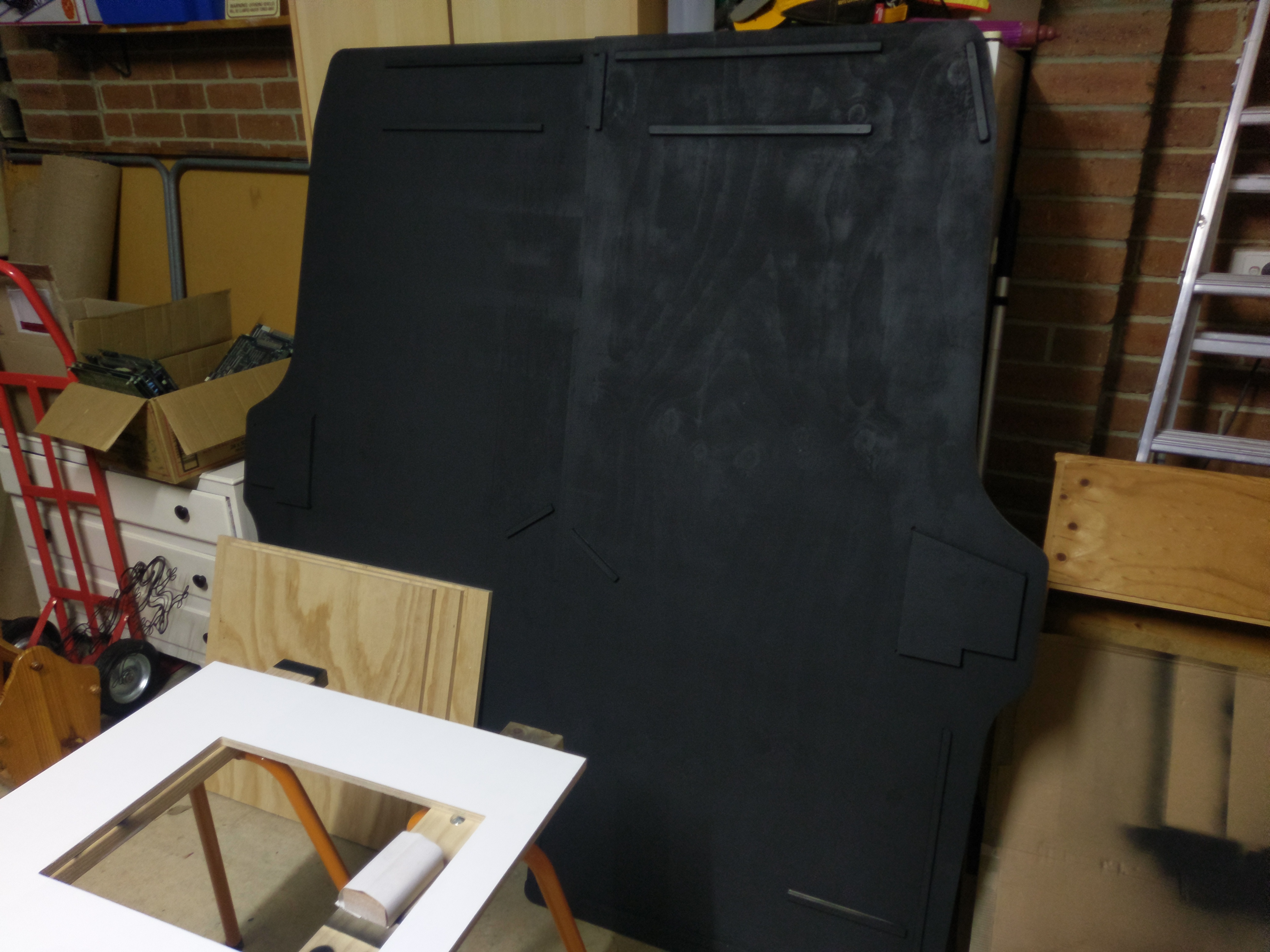
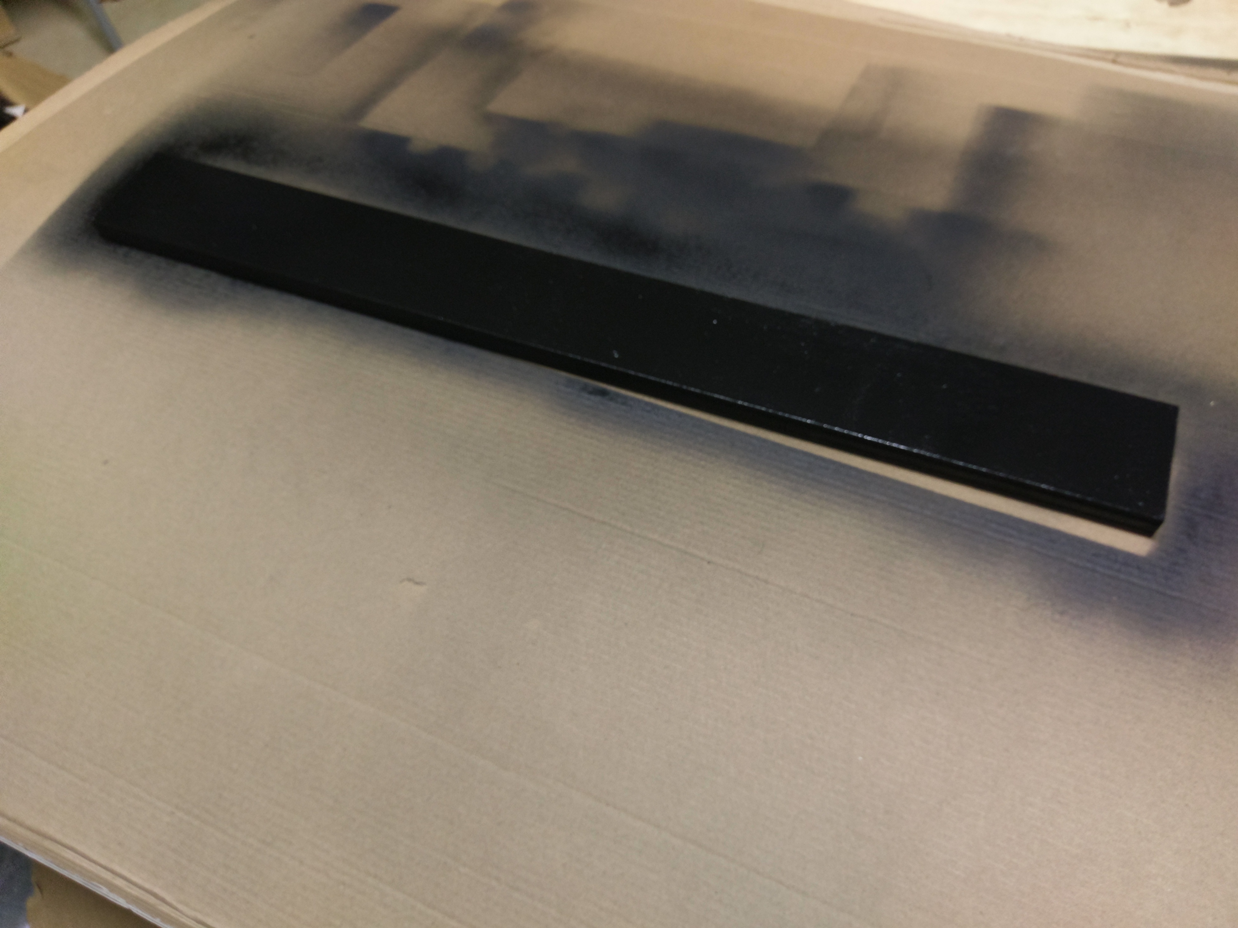
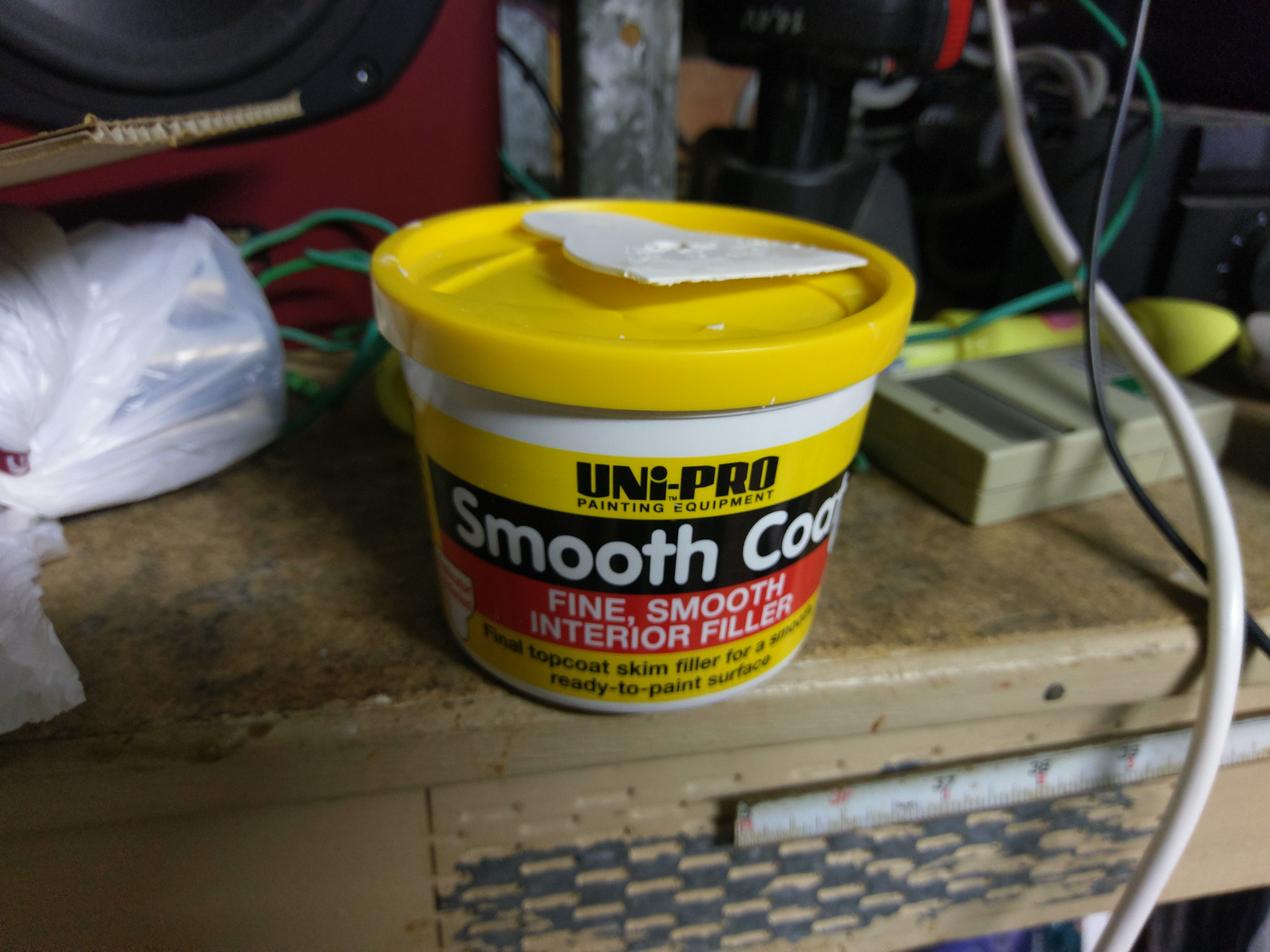
I will be applying the final coats of DK Blue to each side piece once the cabinet is assembled as I still need to route out the groove for the t-moulding and wouldn't want that process to ruin the paint job. With that being said I still decided to get an undercoat on each side and then filled in some of the imperfections with some filler, then will give it a light said before assembly.
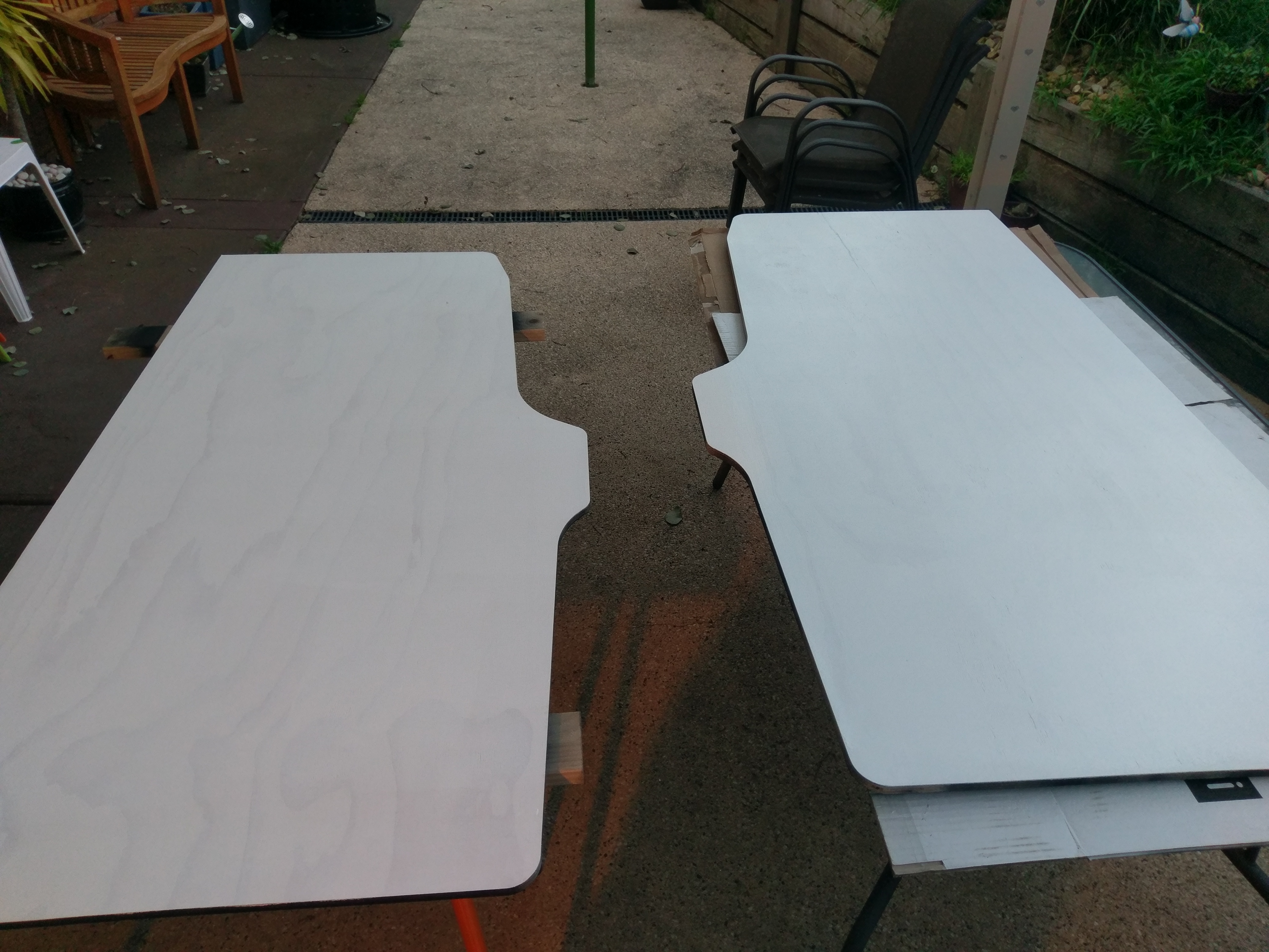
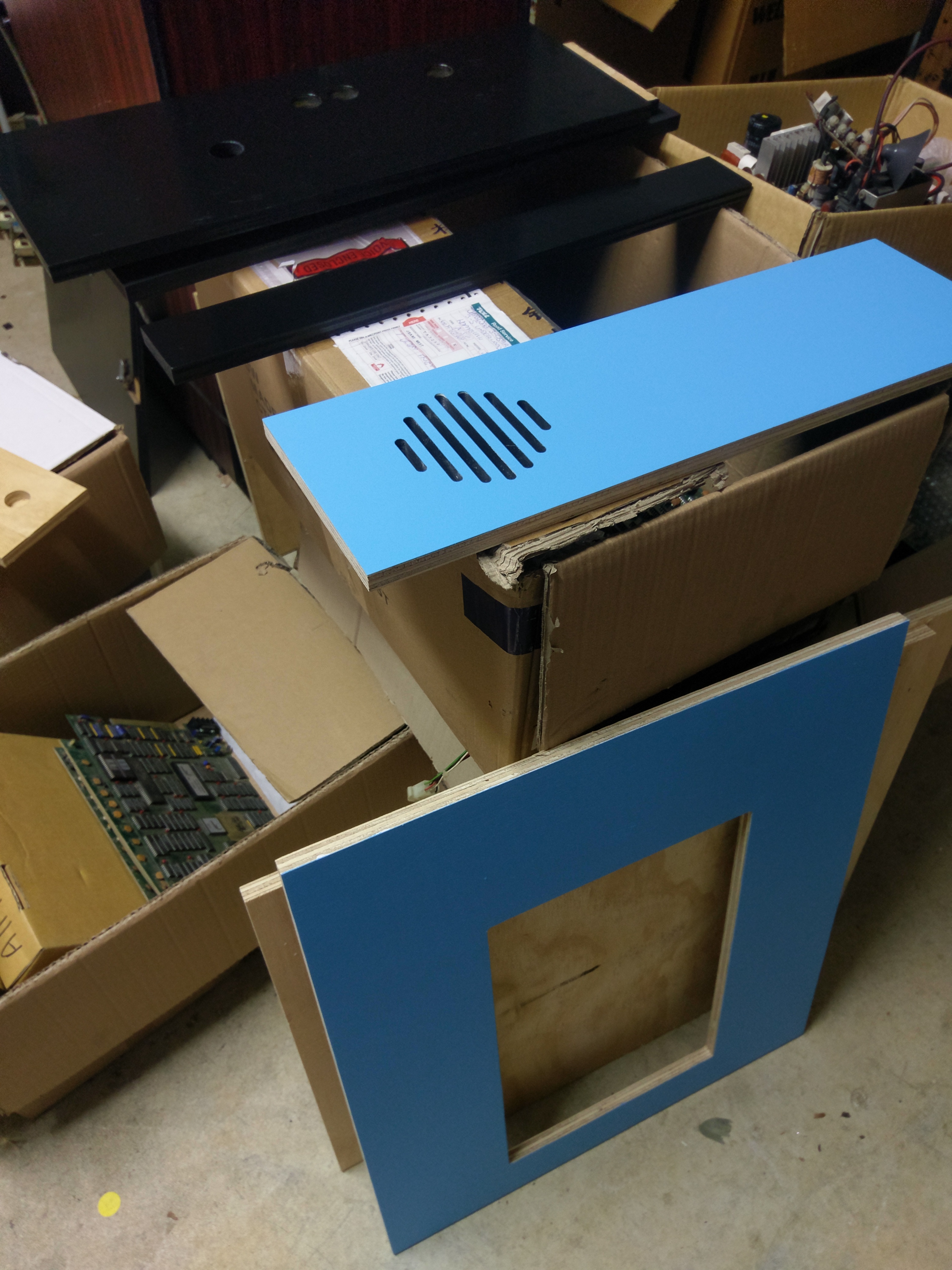
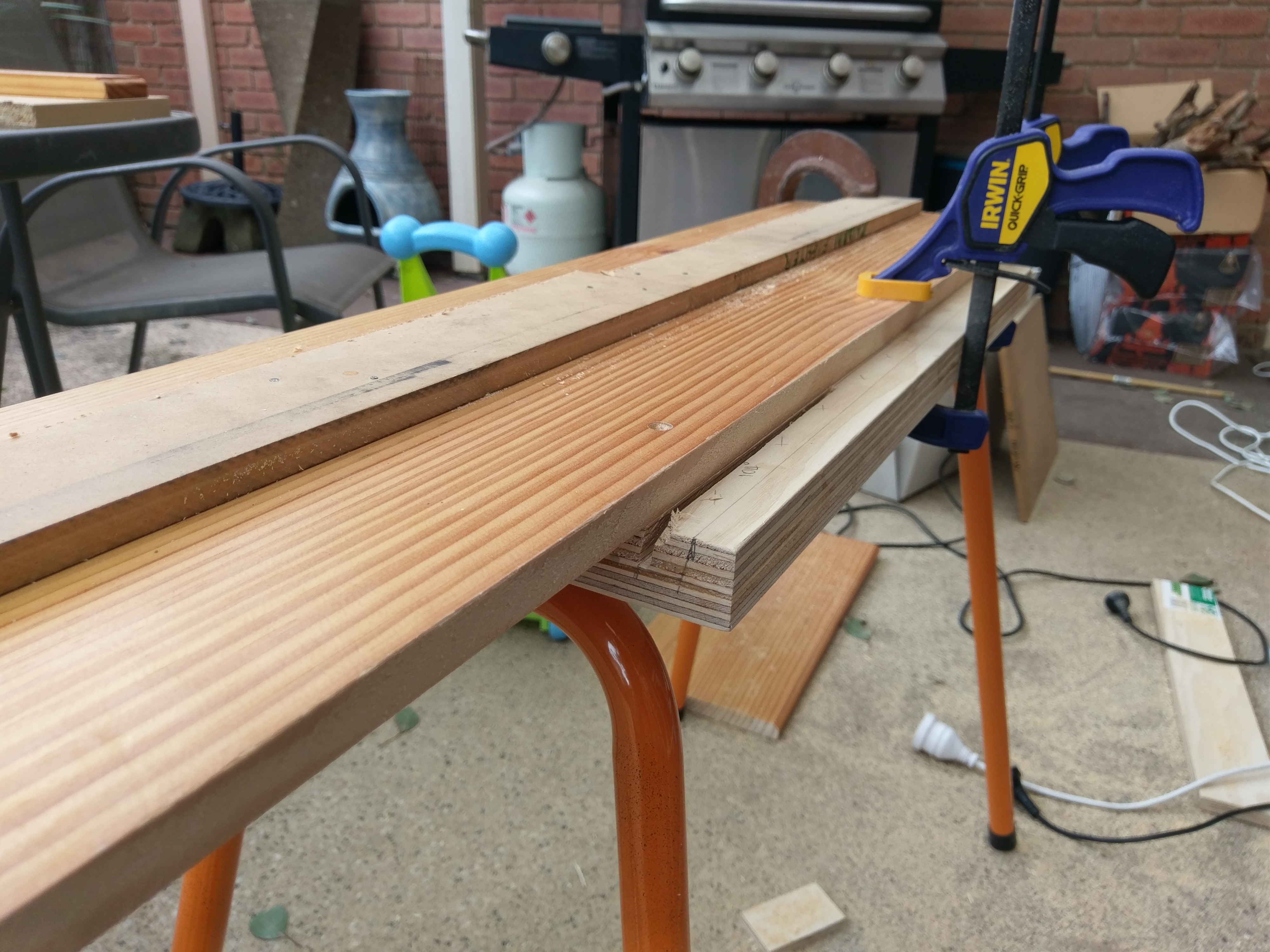
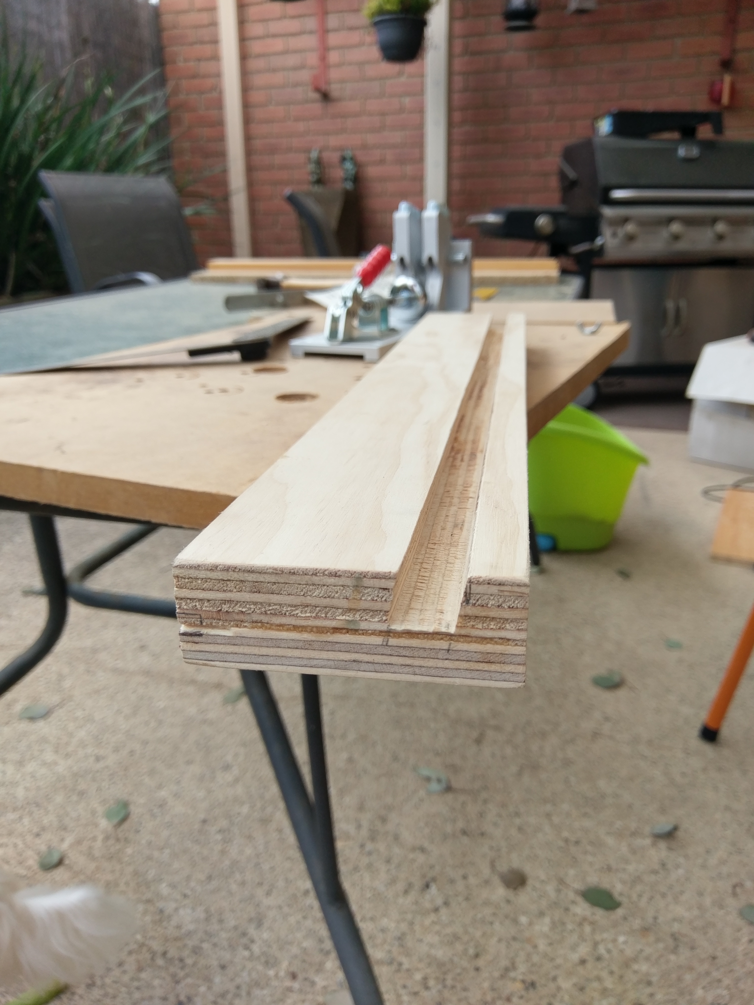
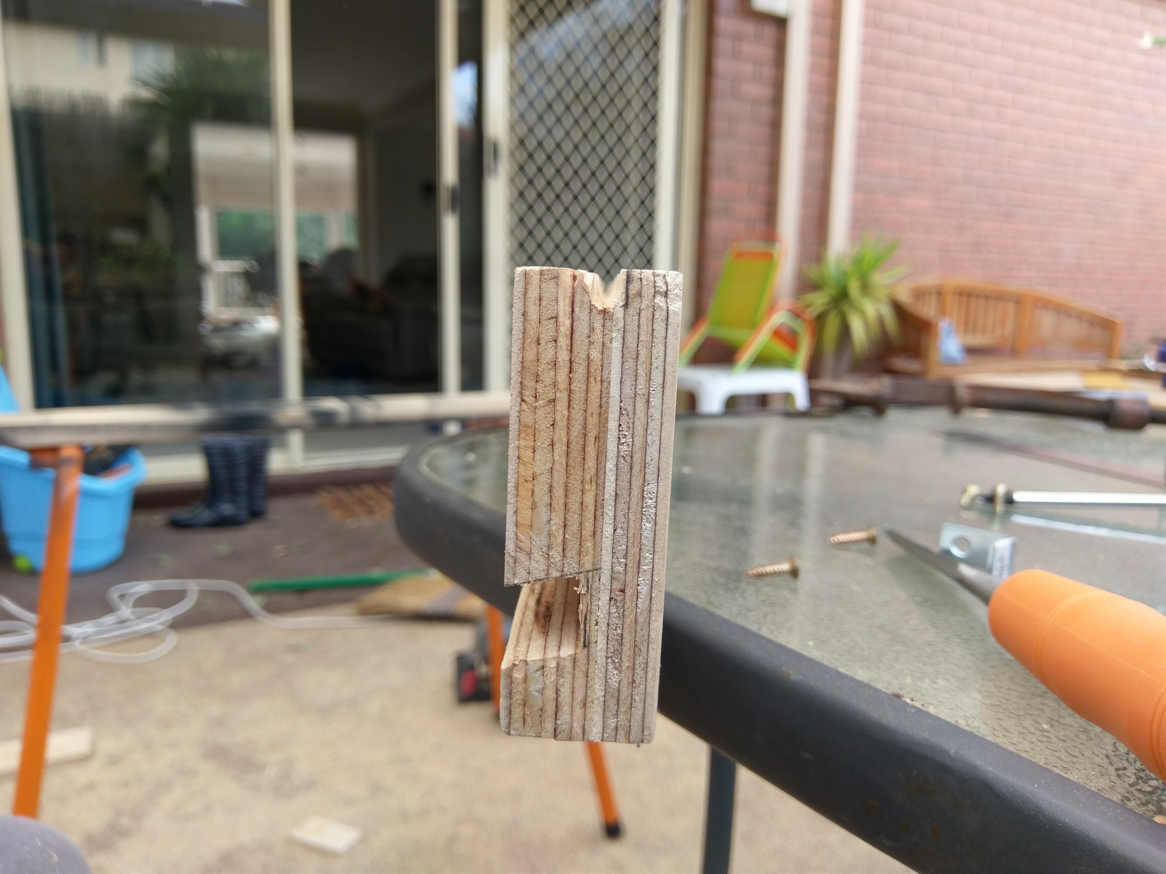
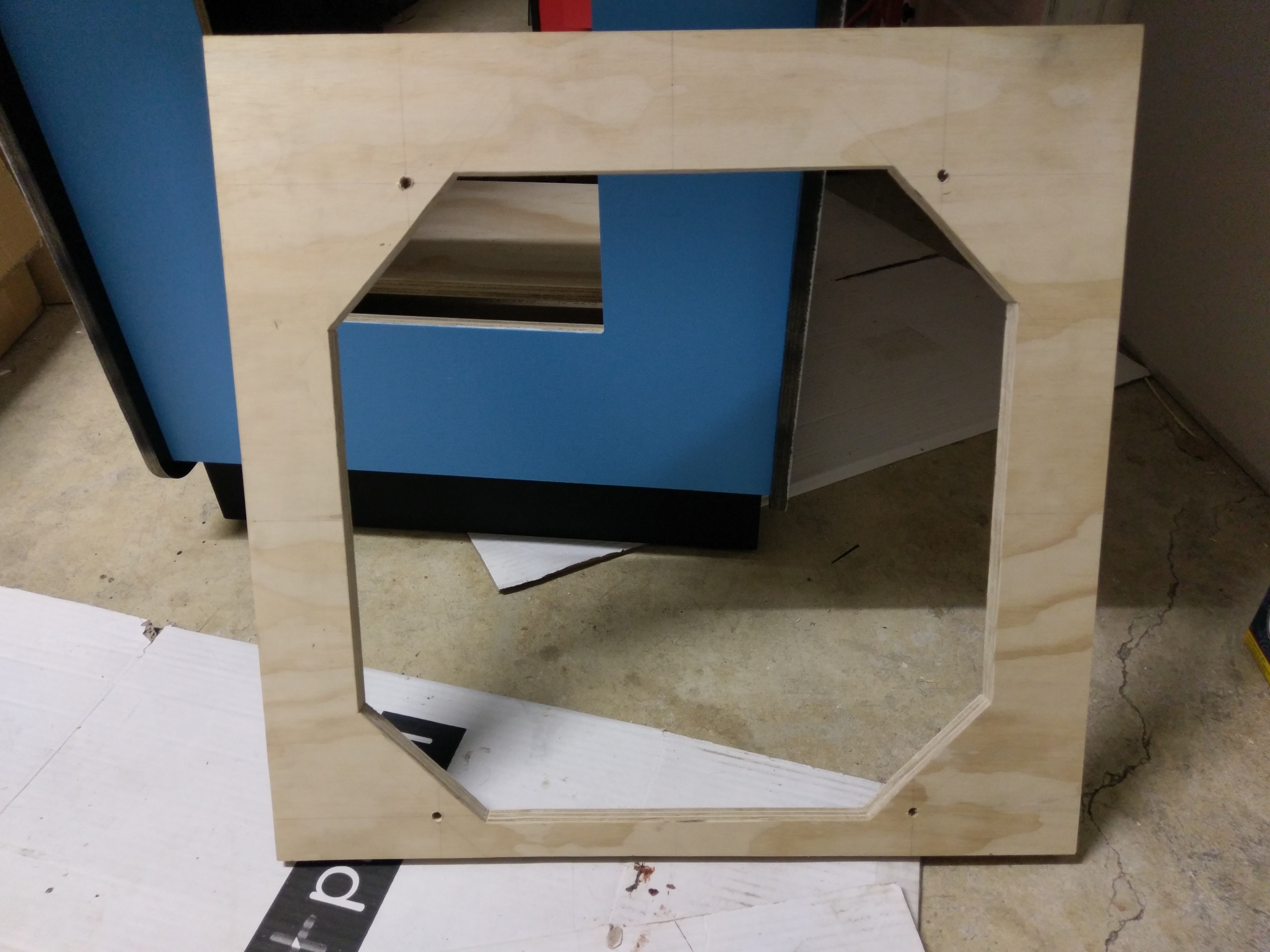
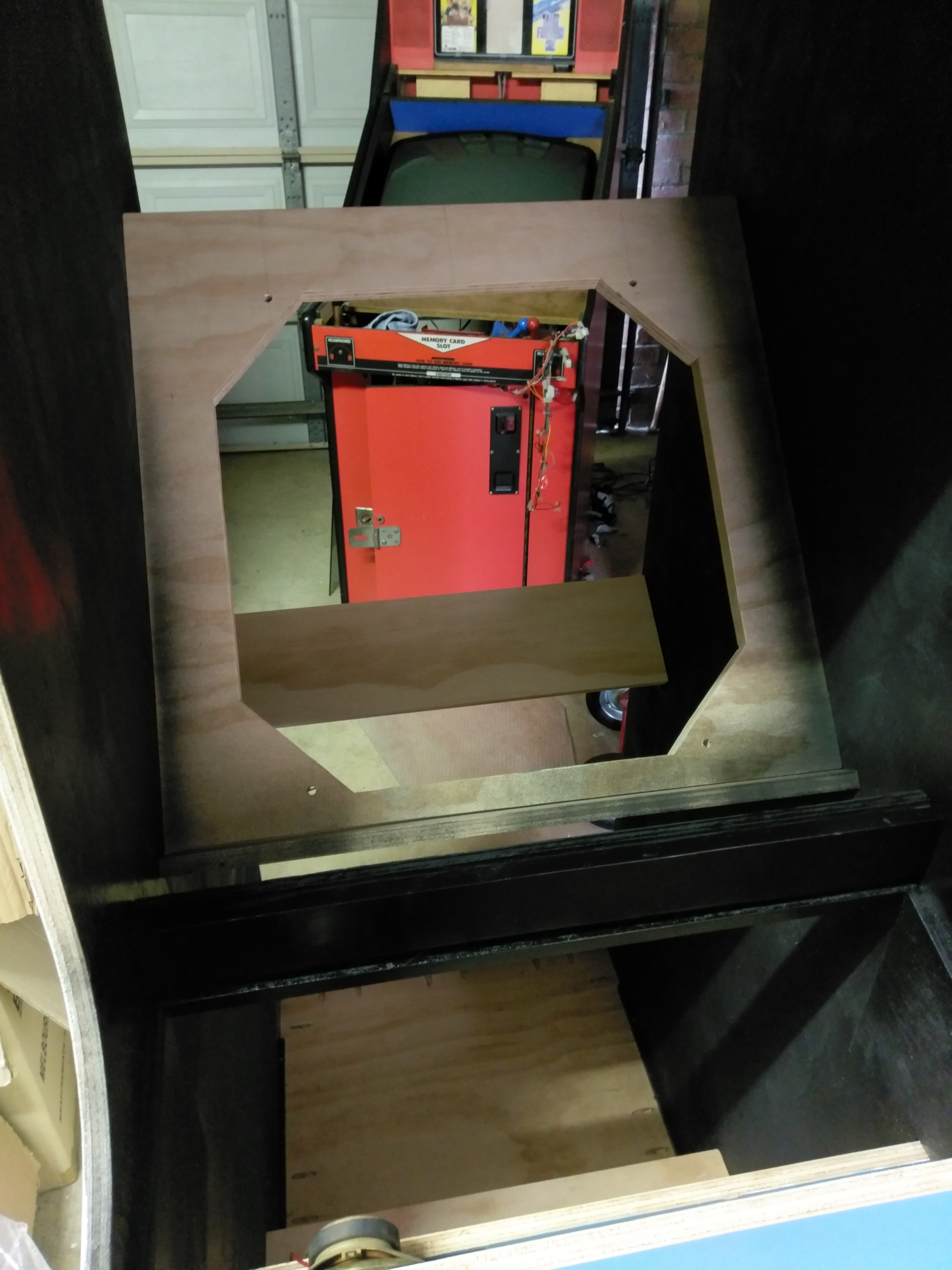
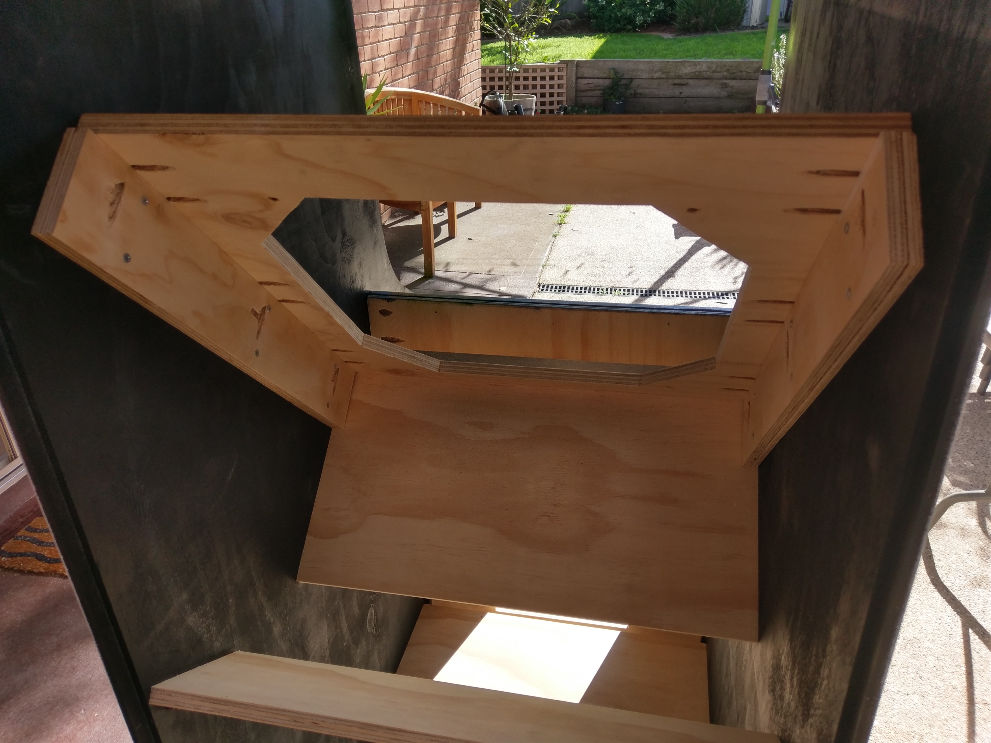
I painted the front coin door panel and the speaker grill panel with their final undercoats and coats of DK Blue, as these will be harder to paint once assembled. My final bit of prep before assembly involved me having to manually re-create one of the of the pieces that sits across the front of the cabinet and has a slot to house the control panel. This is labelled “Control Panel Support” on the plans. The trick with this piece is that according to the plans it is actually 29mm thick and has two tricky cross cuts. I ended up using two spare pieces of 18mm and 12mm ply and glueing them together to make mine but in hindsight would have just got x2 cut on the 15mm ply by the CNC guys. Now making the cuts required was another challenge all together… I don't have a table saw so had to make a jig for my circular saw to make the 104 degree angle cut required and then another jig to make the slot cut along the top to house the monitor bezel. See the pics below..
Then finally I gave this piece along with control panel a couple of coats each of the black gloss spray paint with a light sand in between coats. This piece in particular actually has the instruction card/sticker on it so I wanted it to be extra smooth!
Next is the cabinet assembly!
Cabinet Assembly:
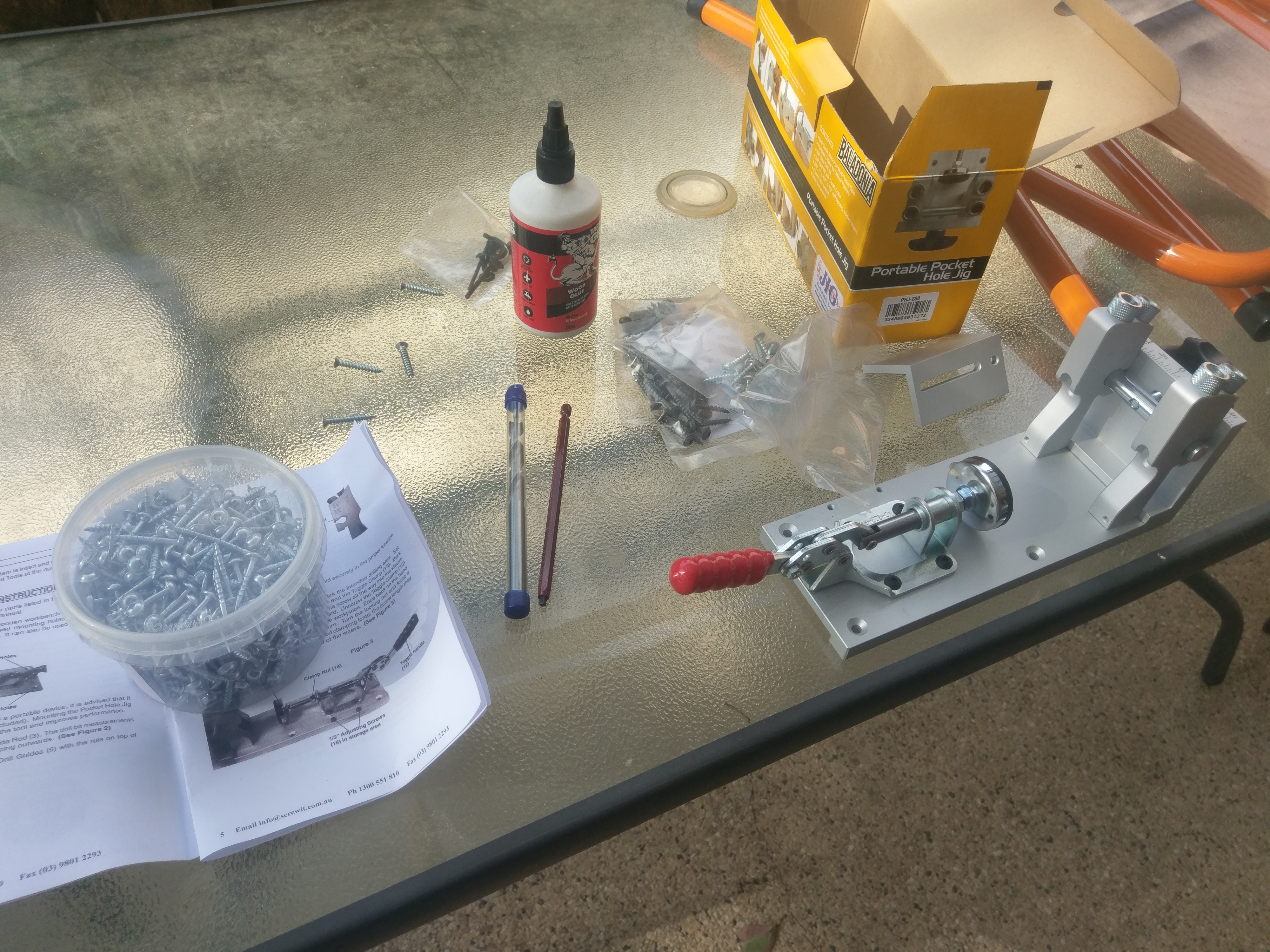
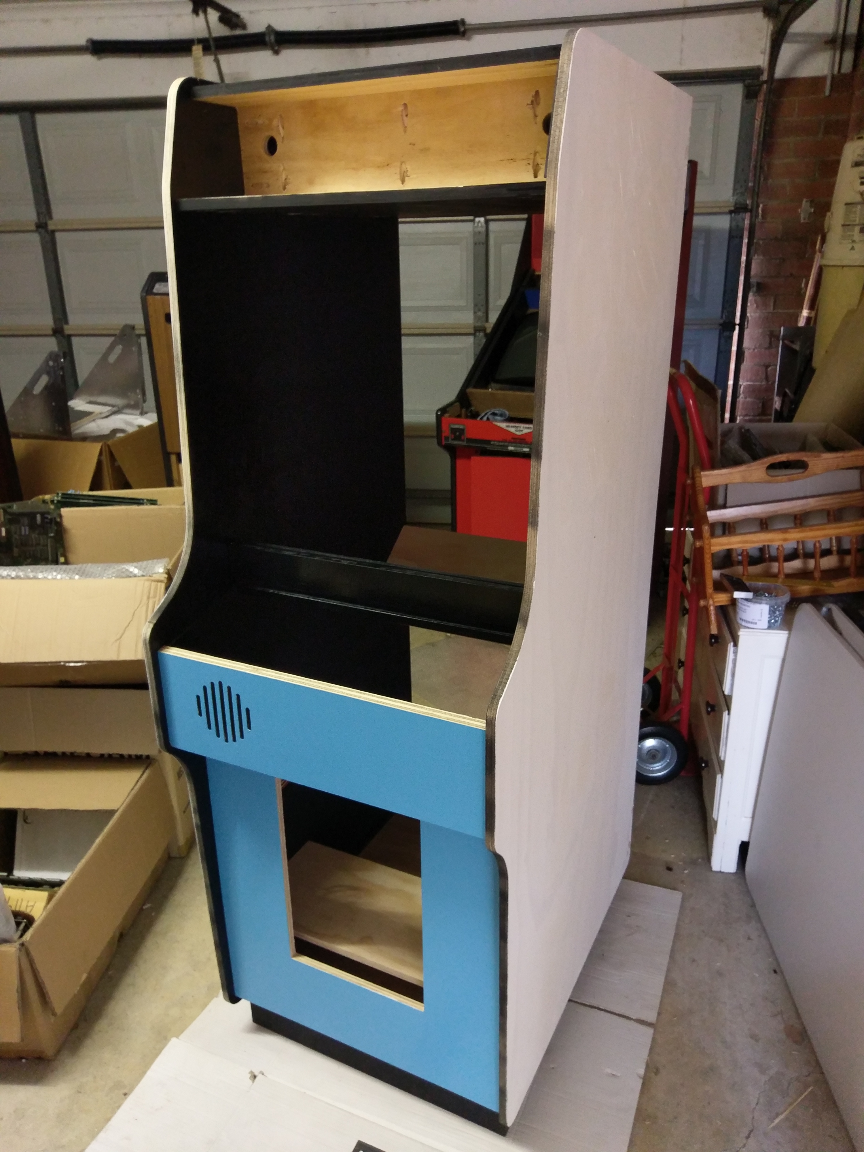
As suggested by Brian on his website I decided to purchase a pocket hole jig (kreg jig) and use screws and glue for my assembly. I am so glad I did in the end as assembly wasn't overly difficult once I figured out where everything went.
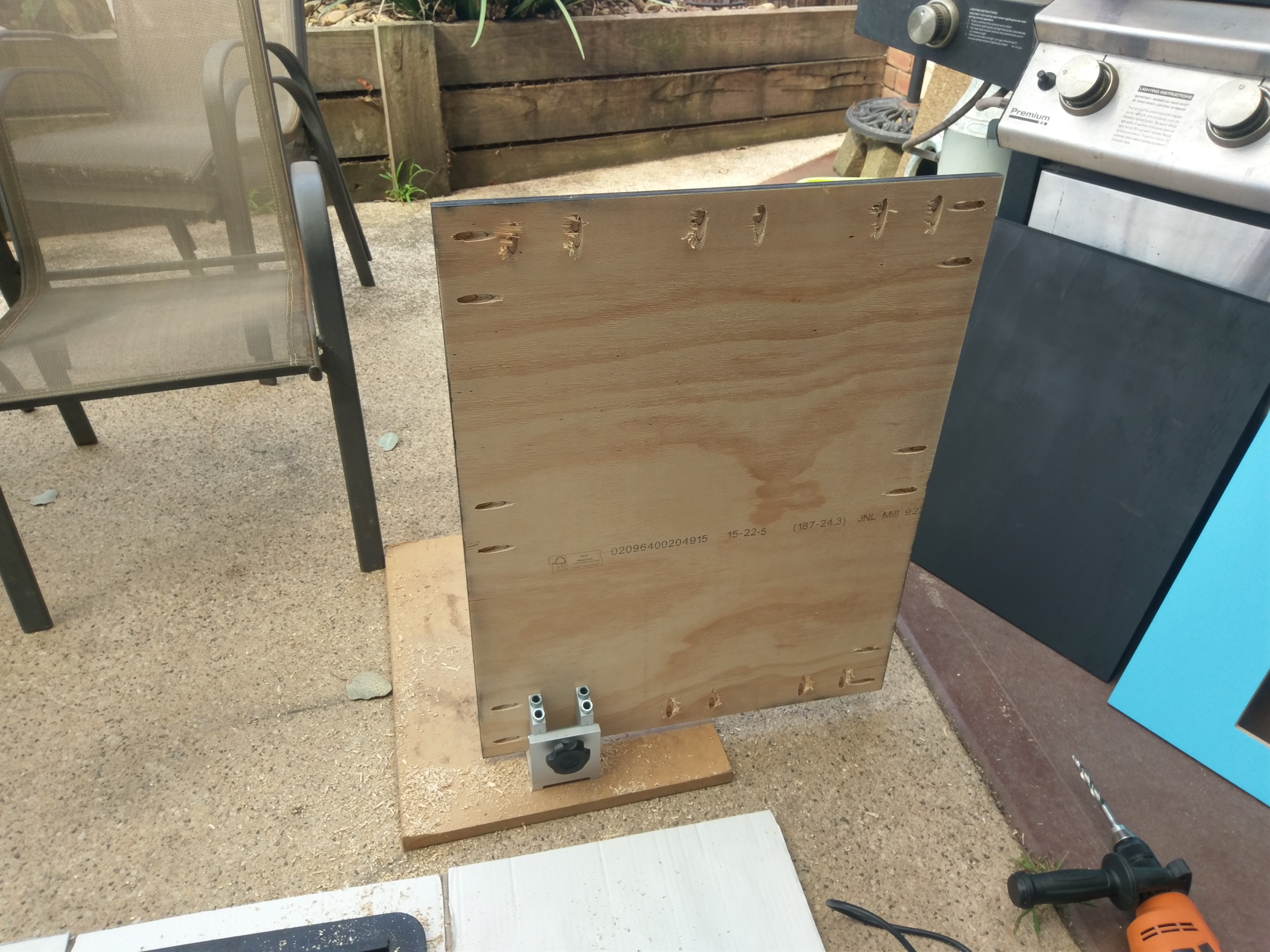
There were no IKEA instructions with this one so I had to use reference photos as well as one of Gatean's 3D images from Brian's website to help figure out how everything went together. Mind you, most of the blocking on the side pieces, help out alot with that.
I laid one of the sides on the floor and went from there. Once I had all of the cross pieces in place and screwed/glued down I was able to put the other side down. I had to loosen off a few of the screws in the bottom piece to make the other side panel fit but for the most part it all slotted together quite well.. This is where the beauty of machine cut timbre comes into play.

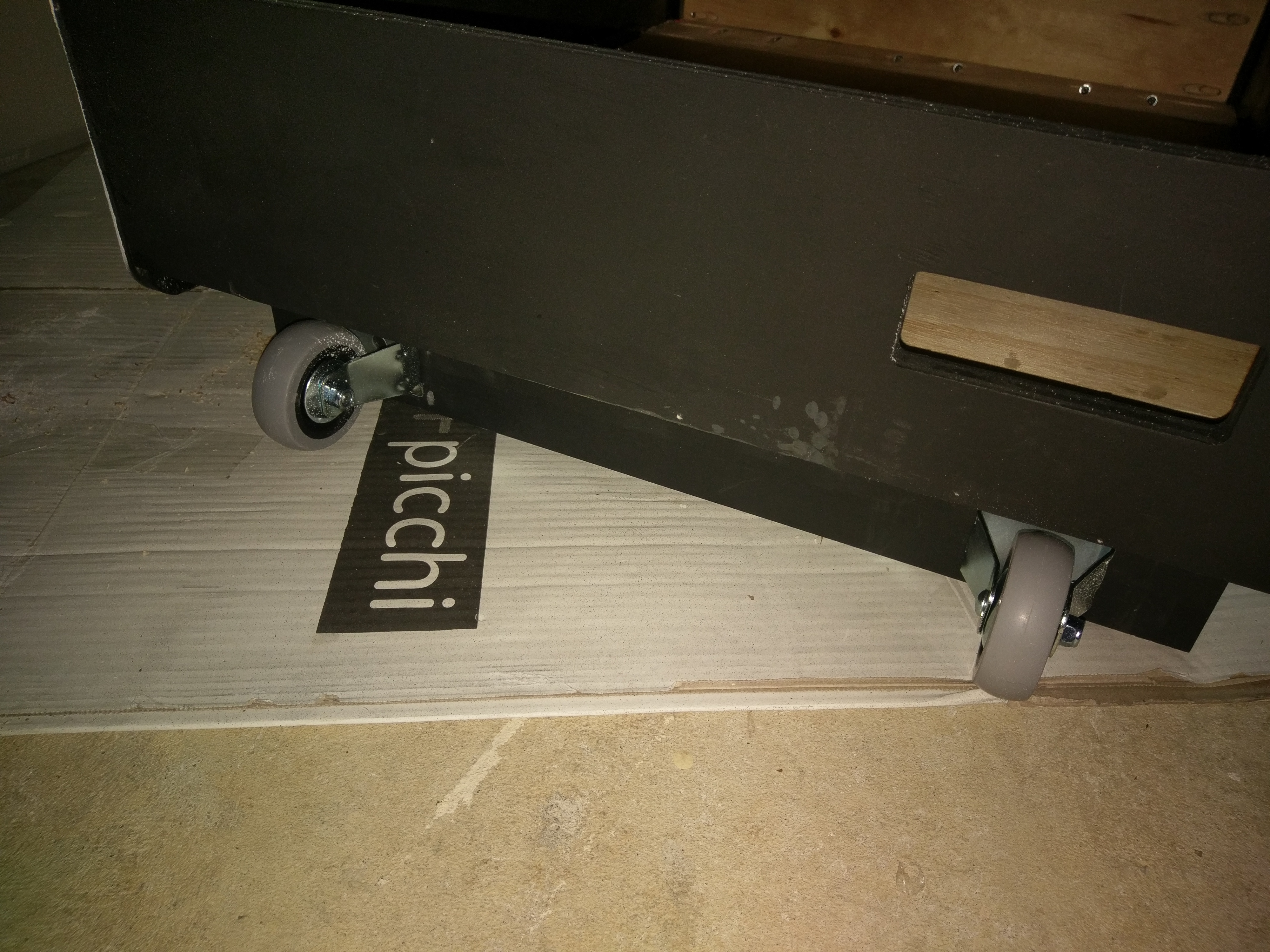
Now that it was assembled I thought it would be easier to move around if I put the base on it and some wheels. So that was the next step.
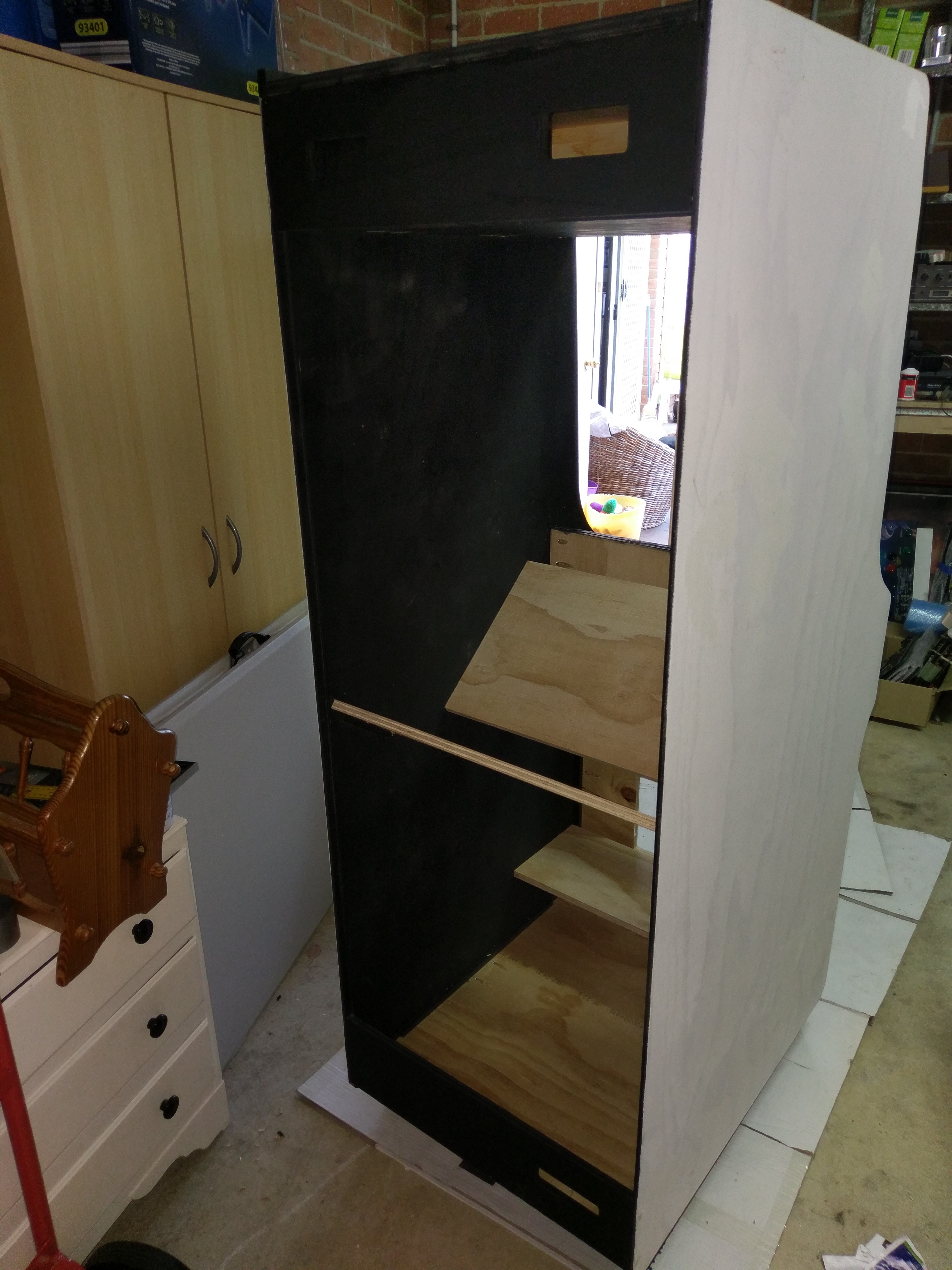
Next I looked to build a mount for my monitor. Since I was going with just a standard 19” CRT and not the original Sanyo20EZ that Nintendo used back in the day I decided to make mine out of timbre and build a support for it that didn’t require me putting bolts through the side of the cabinet. This way the side art would go on nice and clean and not have any ugly bolts sticking through it like the originals do. For the mount itself I borrowed a few measurements from the one in my LAI lowboy and then cut out the hole and bolt holes in a piece of timbre the correct width for this cabinet. I went with an 18mm ply here just for some added strength. When installing it I used the original monitor mount bolt holes to get the angle right and then I fixed it to two support pieces as seen in the pics below.
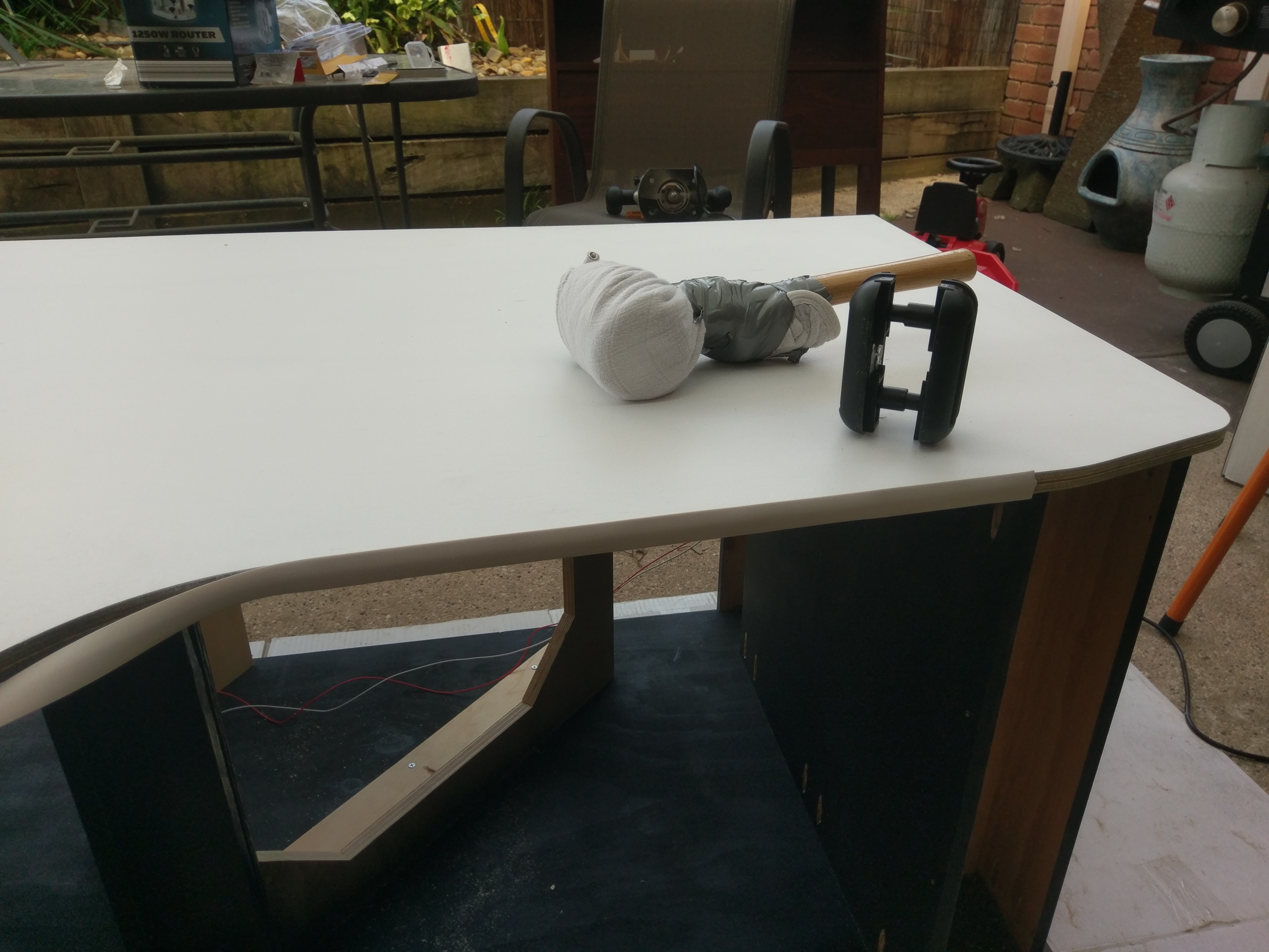
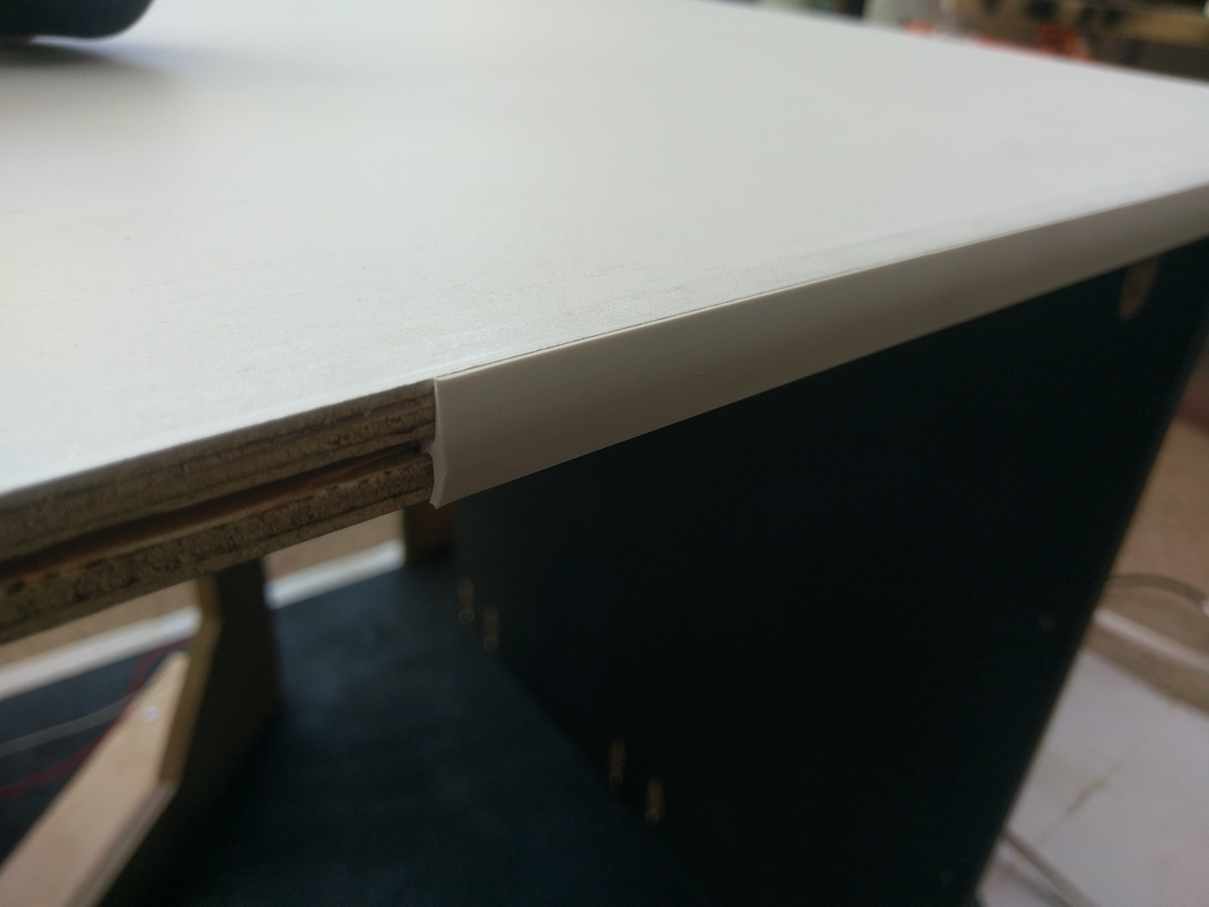
Next it came time to cut my t-moulding slots. I decided to finish the undercoats on the main side panels but not apply the DK Blue before using the router to cut the slots just in case running it along the panels would damage the paint job. Cutting the slot went well for the most part, except next time I would put my base on afterwards as there was not quite enough clearance for the router. Anyway it wasn’t a big deal, the slot was just slightly off centre along the bottom edge and you don’t have to run the t-moulding all the way along it anyway. I sourced some 20mm t-moulding locally for a great price as I couldn’t see the point in sourcing true flat t-moulding from the US as it was expensive and what I had would look very similar once trimmed. I bought myself a special t-moulding trimmer which I saw John's Arcade using on one of his previous videos and it worked a treat. I used it on the straight edges along the front as seen in the pictures below, the trimmer does not work around corners unfortunately. Anyway it was quite easy to put it in, trim and repeat, once again I did this before painting the DK blue as using the trimmer does mark the surface you are running it along. Another tip is to wrap your mallet with a towel or thick cloth, that prevents any marks transferring to the t-moulding when you are knocking it in.

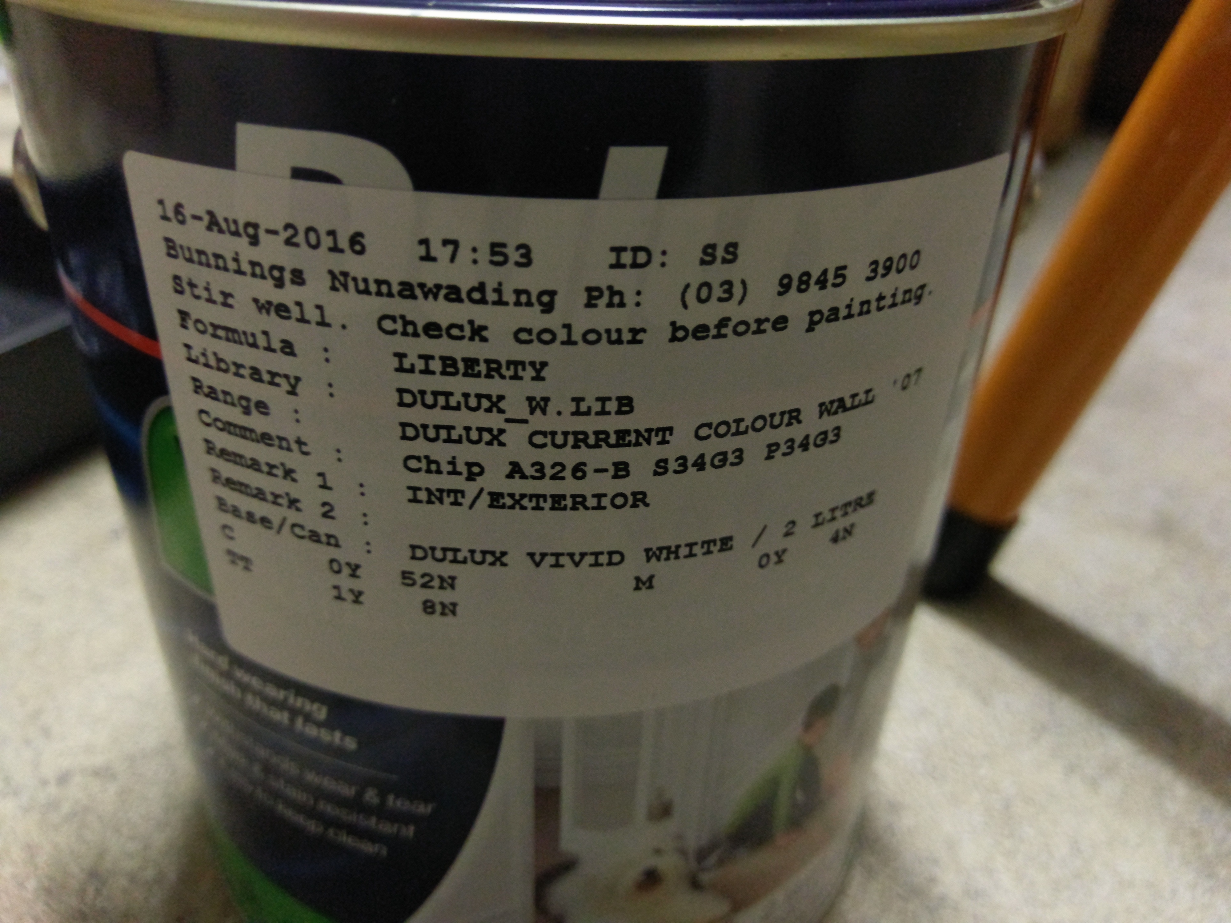
So once I had trimmed the t-moulding I decided to paint the DK Blue on. I just gave it two coats (as well as the two undercoats) and it came up a treat!

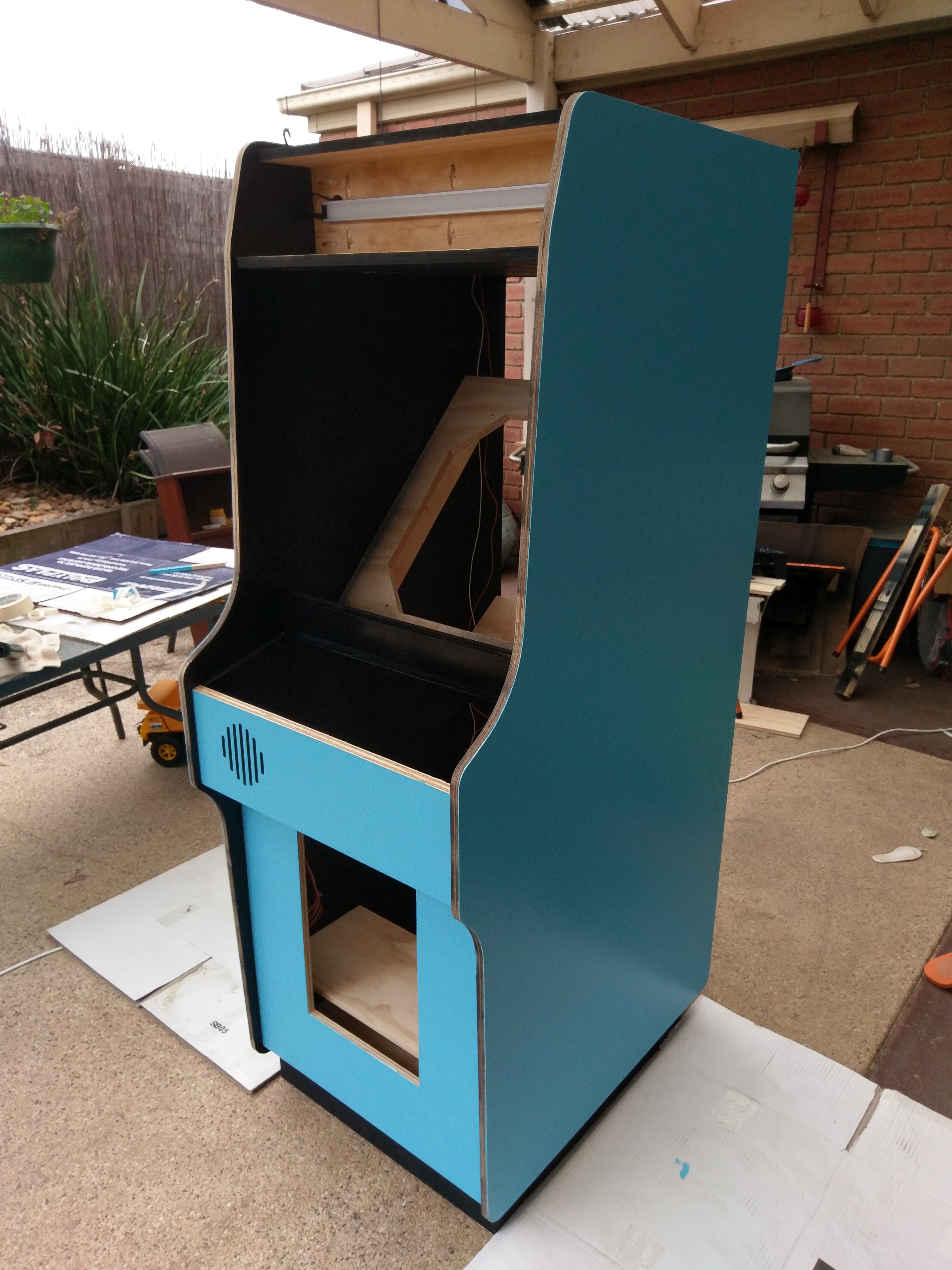
Next everything else came together quite quickly..
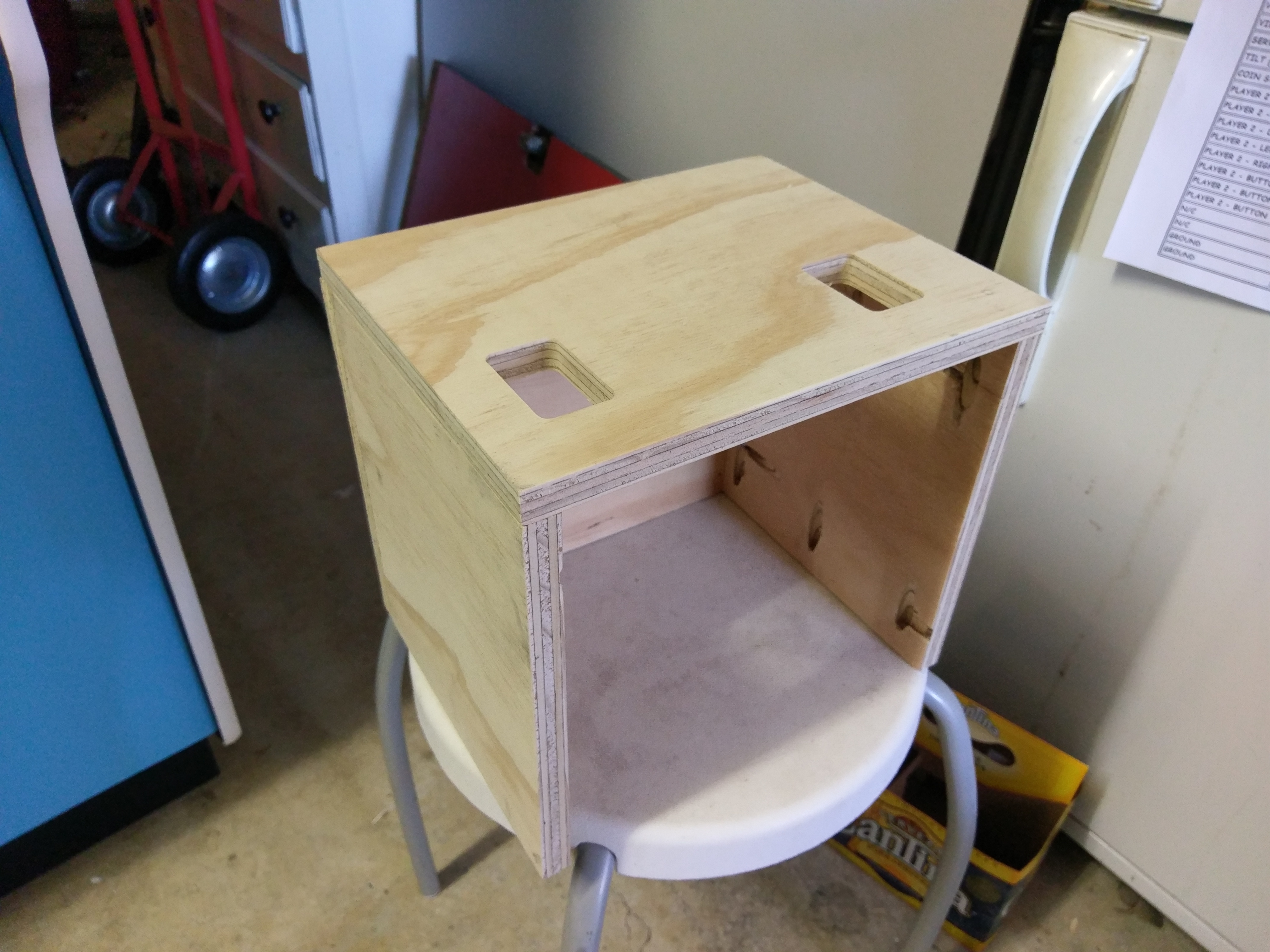
- I assembled and fitted the coin box holder (there were no plans for the coin box itself so I just made one up later on)
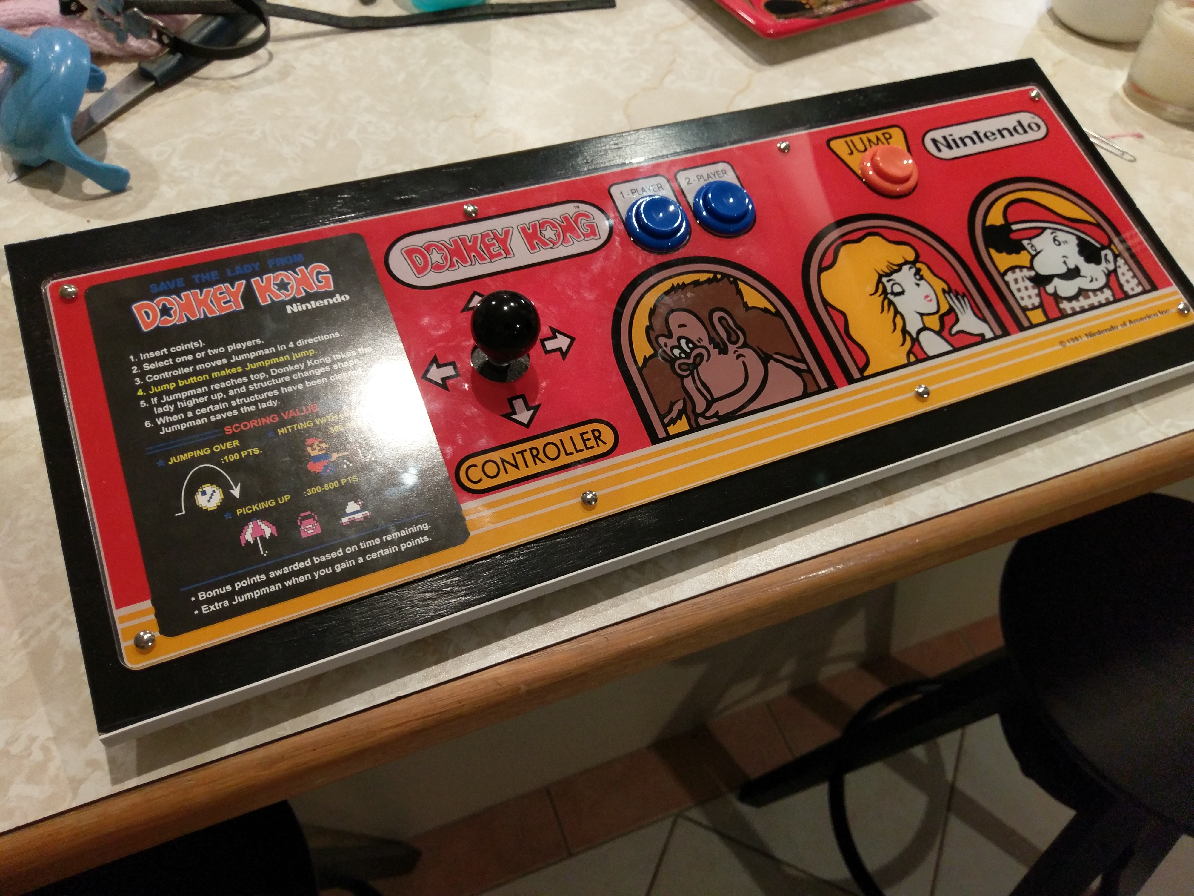
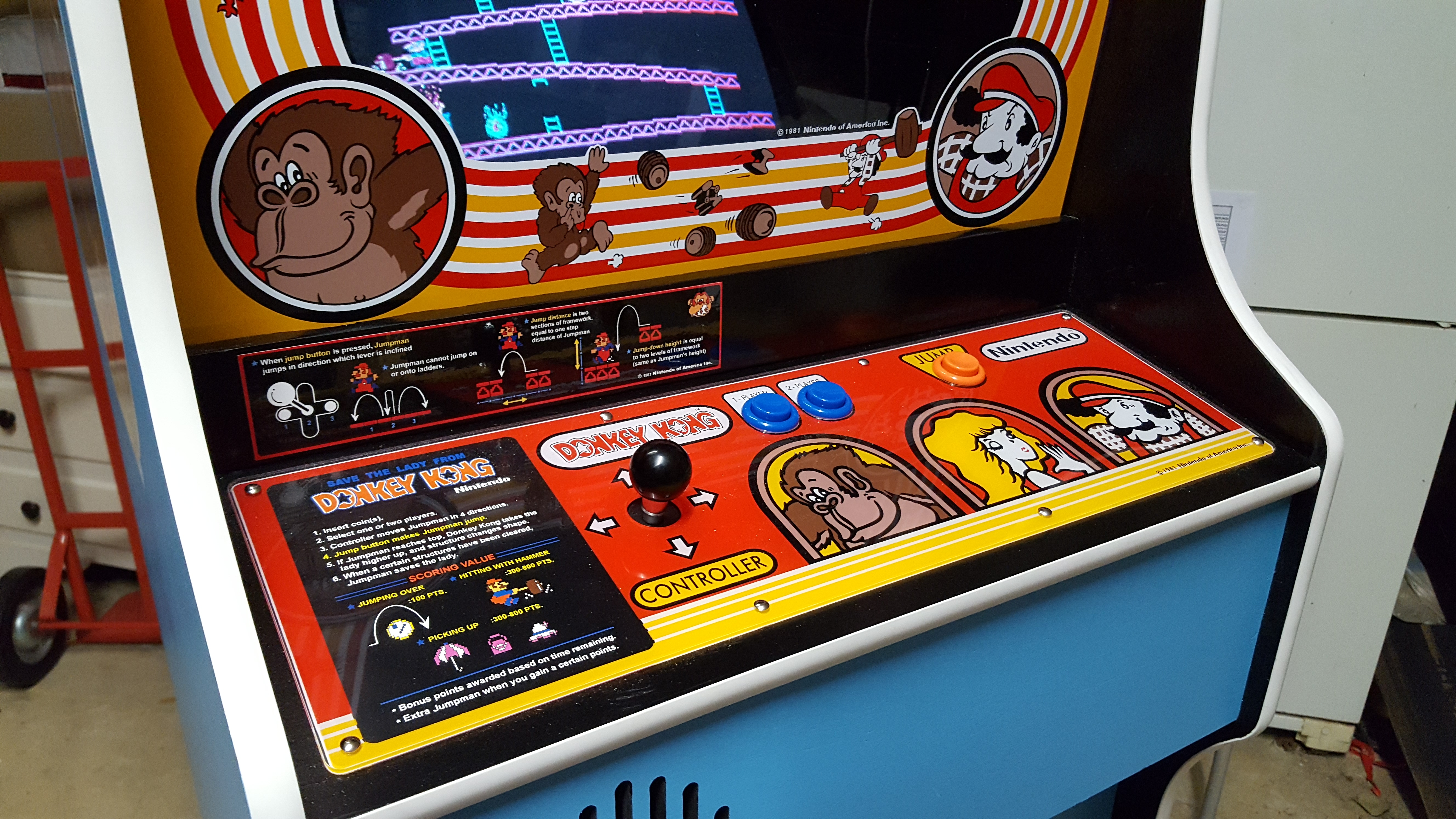
- Assembled the control panel and fitted the control panel latches to the cabinet
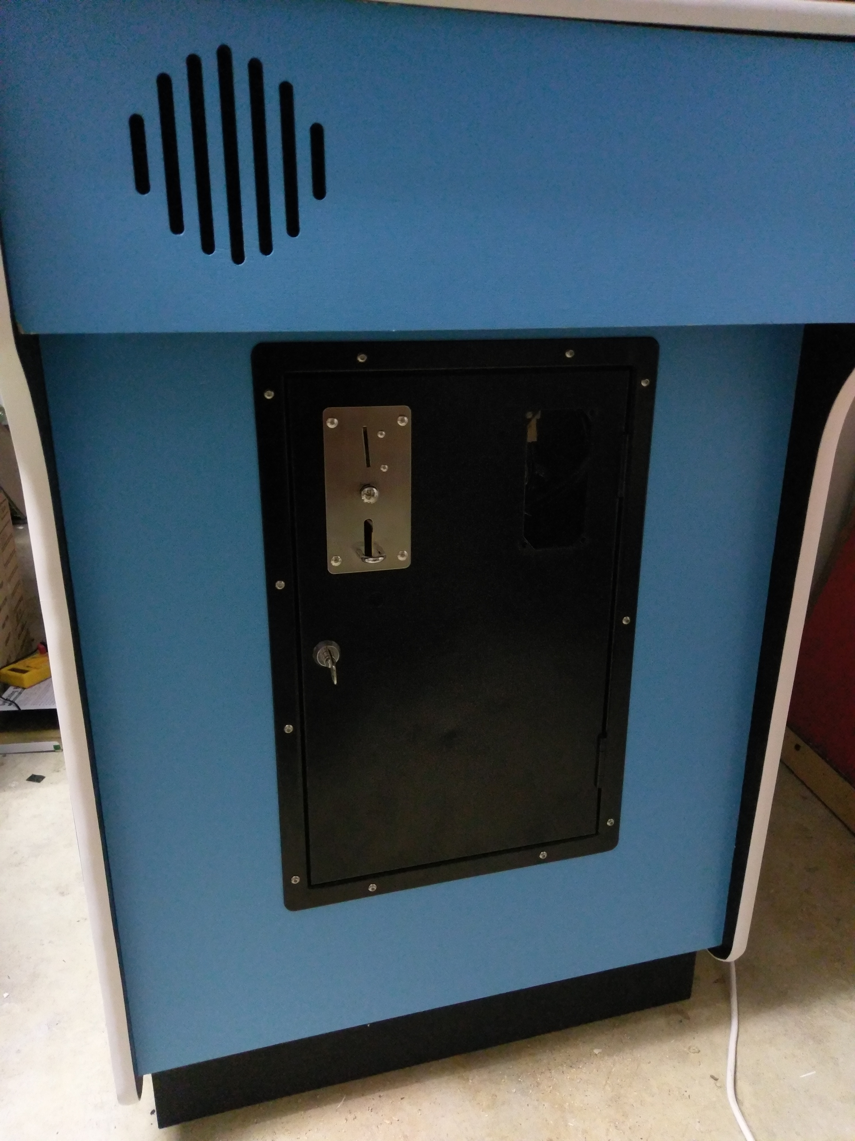
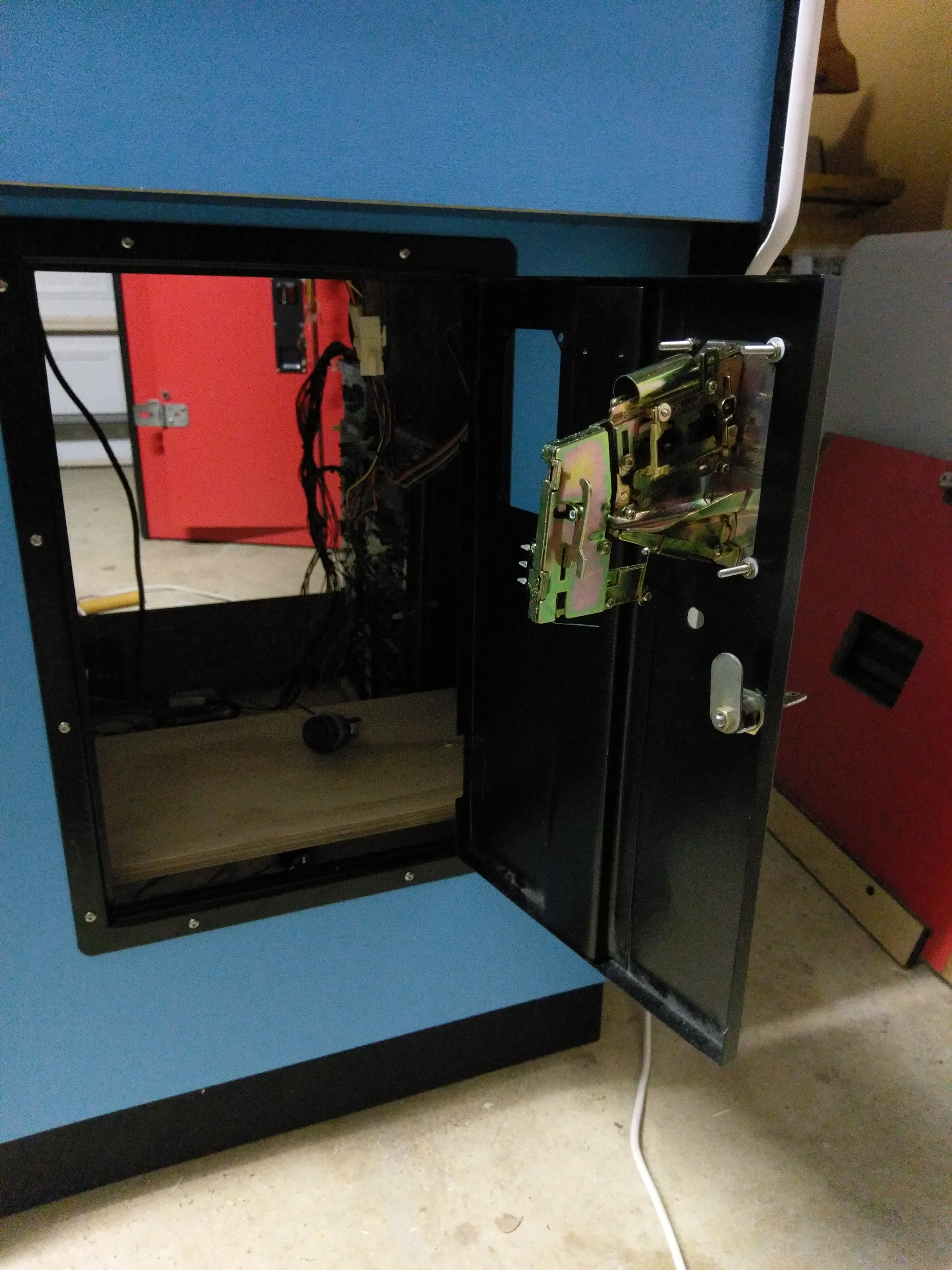
- Fitted the coin door along with a couple of Classic Coin mechs (sourced from OzStick).
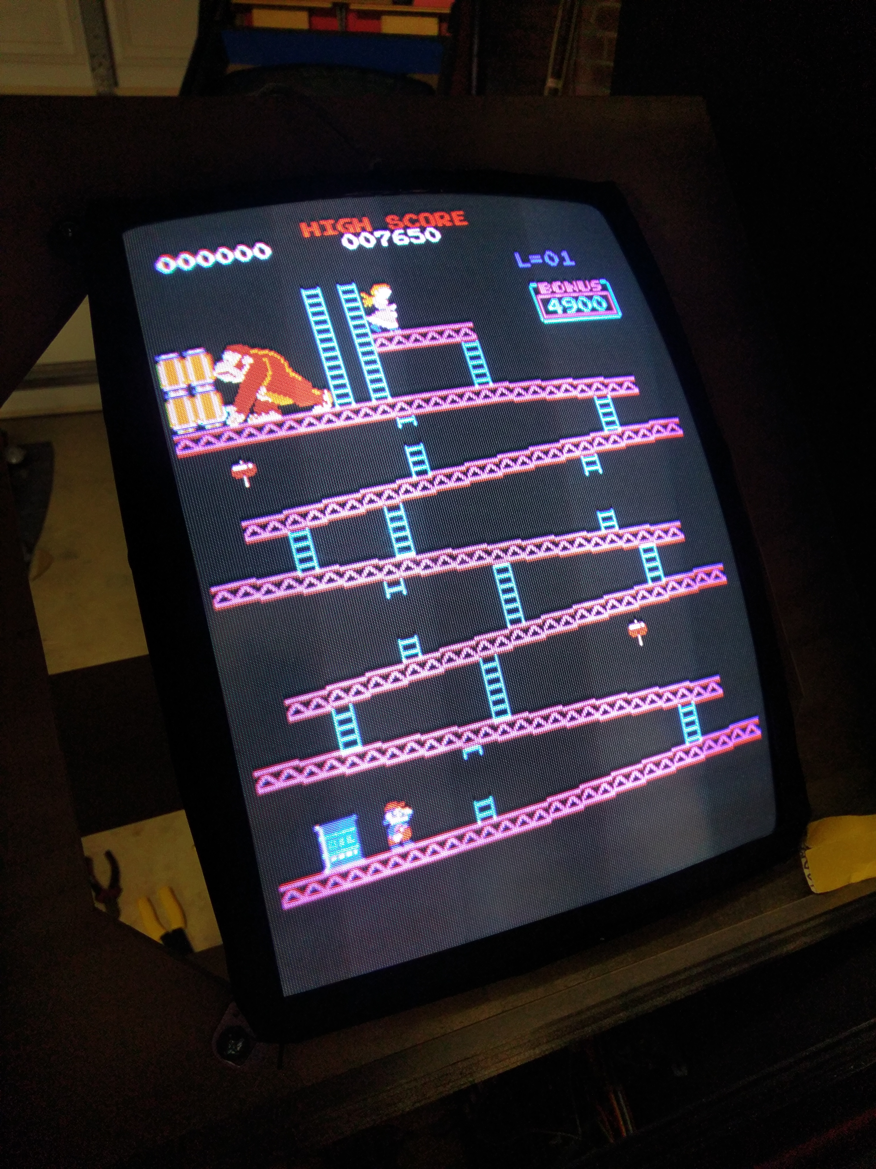
- Fitted the monitor and mounted the chassis
- Mounted the PCB inside the cab
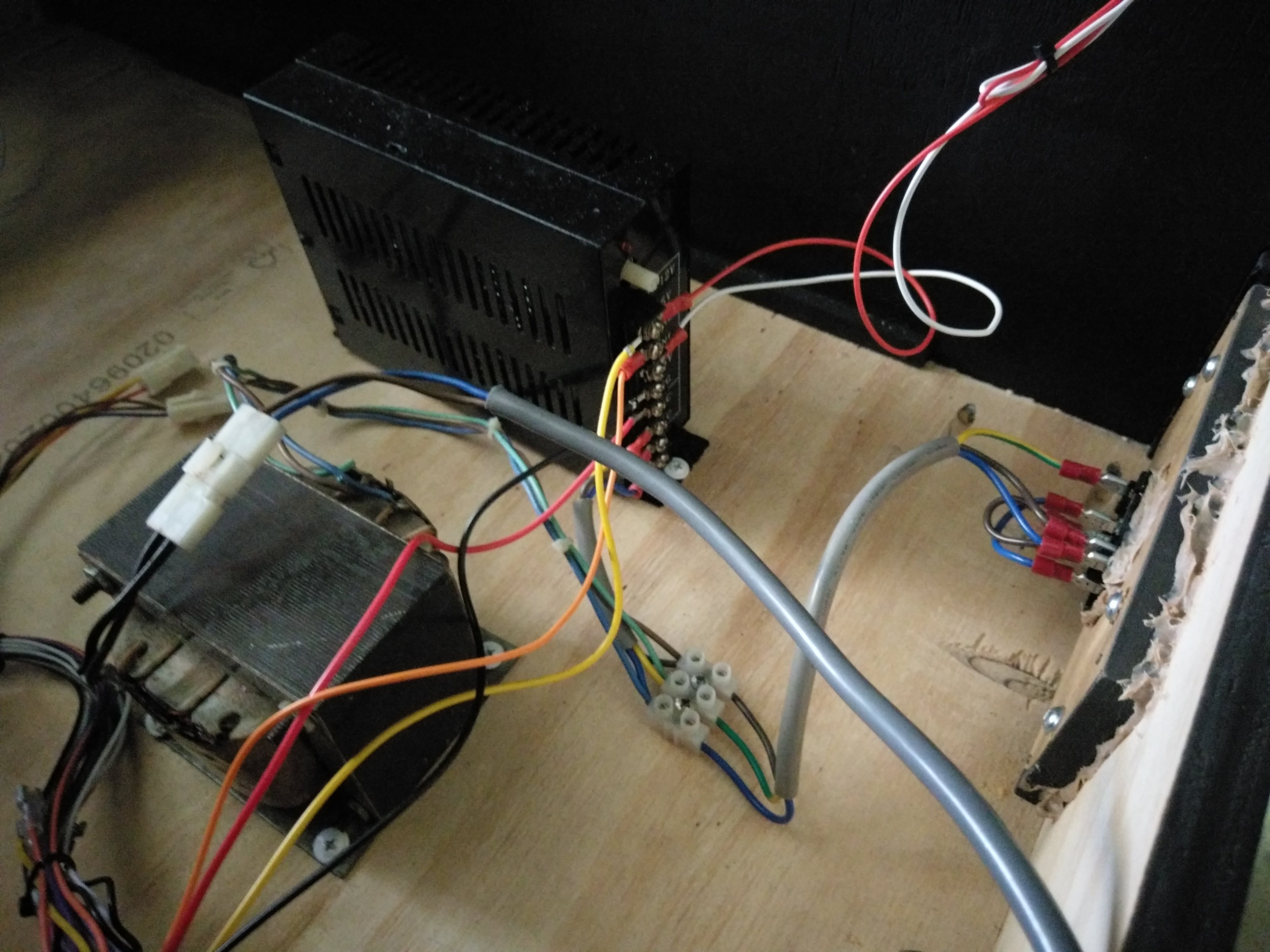
- Using a pre-wired off the shelf JAMMA harness I wired everything up putting molex connectors between the main harness and the control panel (for easy removal) as well as the speaker.
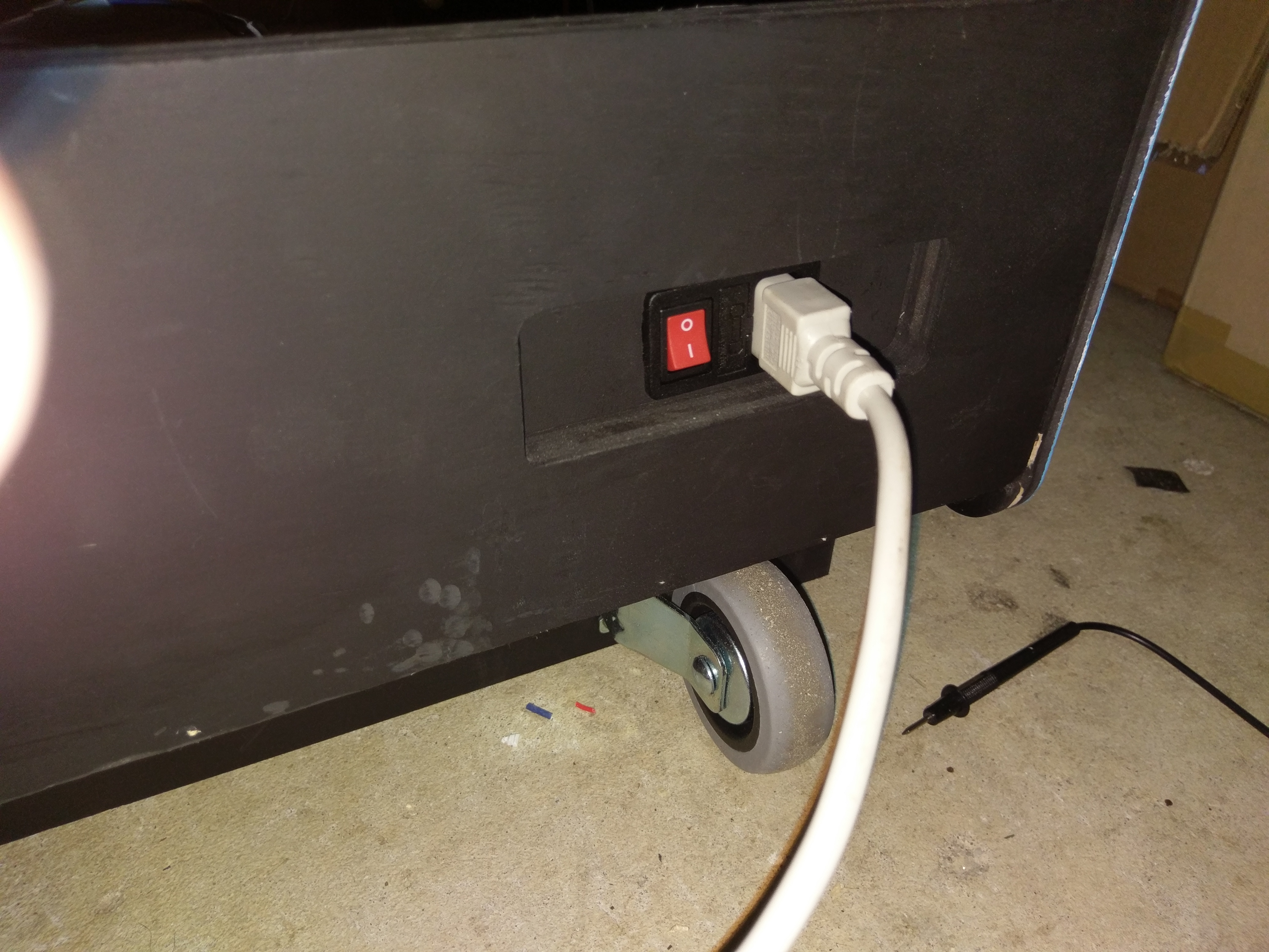
- I decided to use a IC Switch (with a fuse) for the power coming into the cabinet and just fitted a common 15amp PSU along with the 110V transformer for the monitor.
- The marquee light I used was just an off the shelf 12v LED from Jaycar which fitted perfectly into the marquee recess on the cabinet and I was able to just wire it directly to the +12v on the PSU.
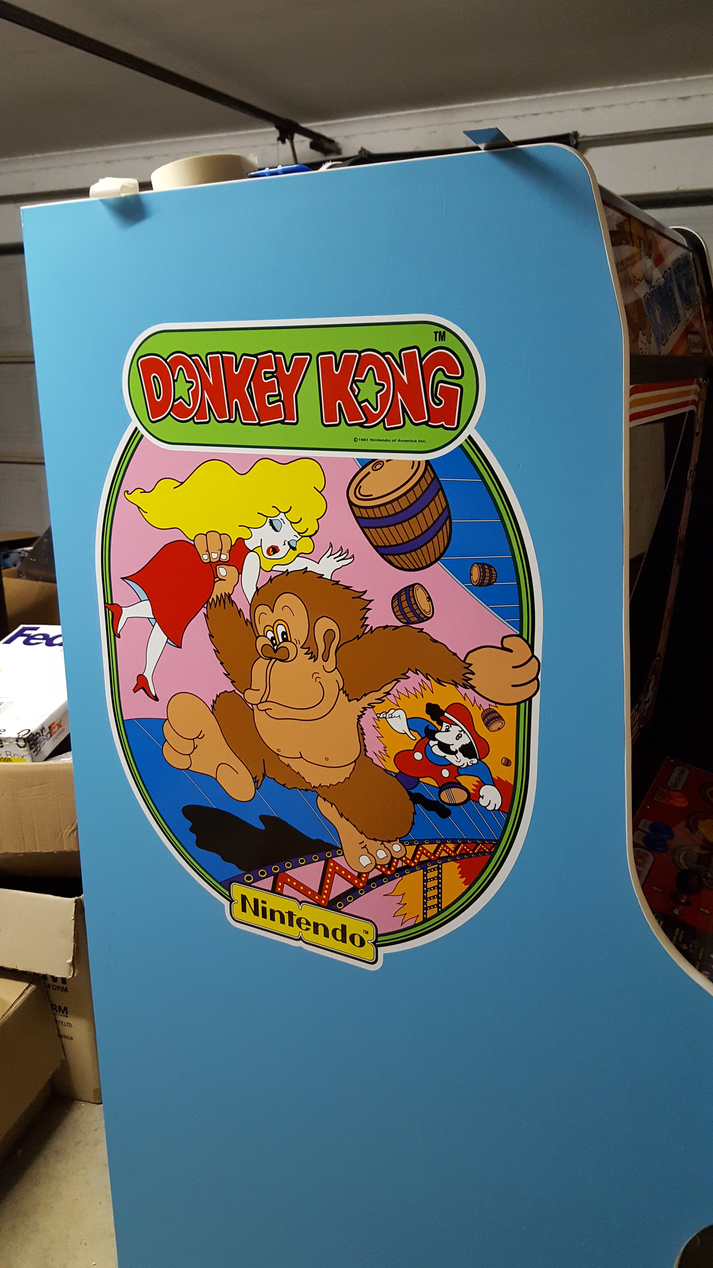
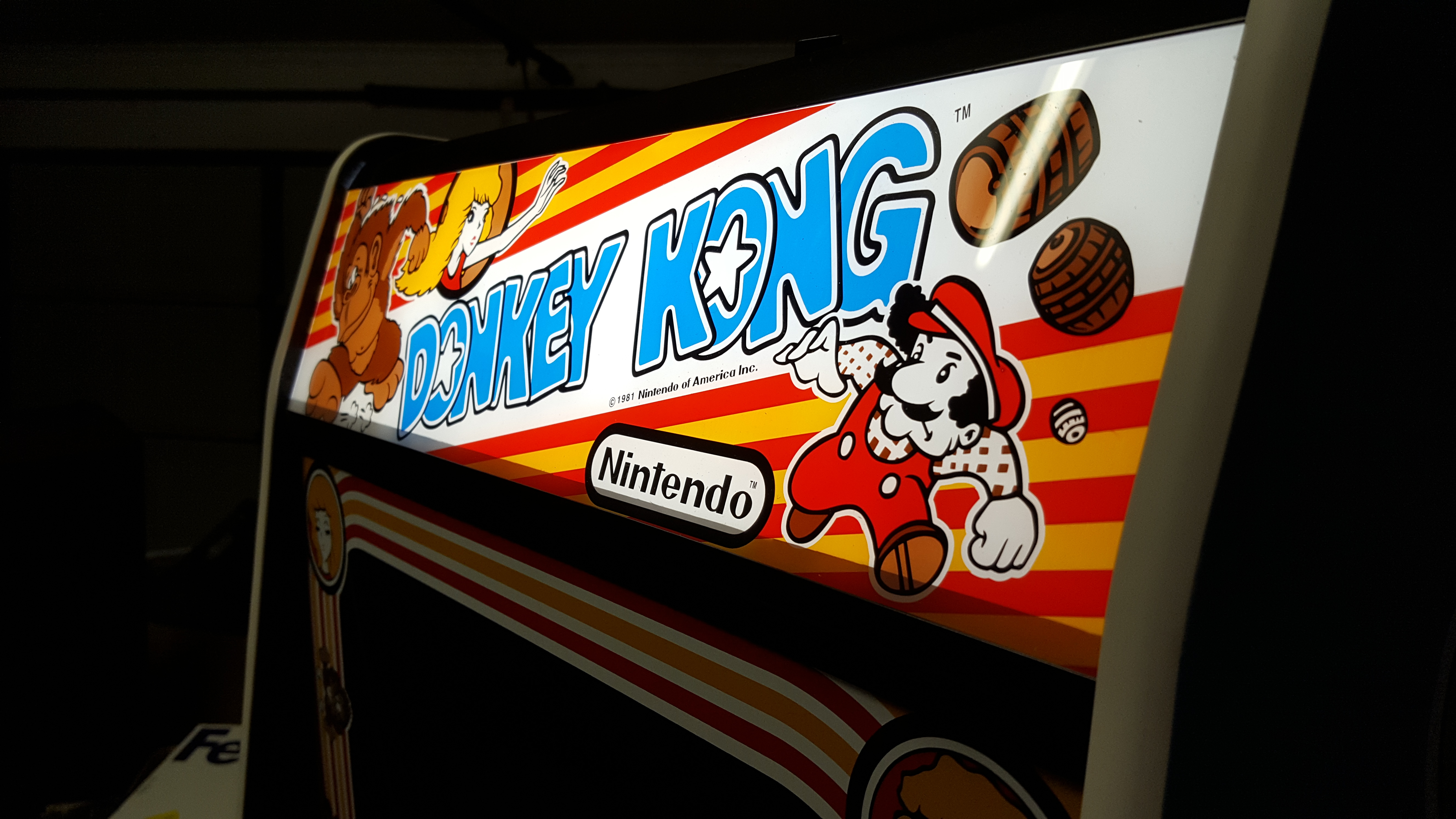
- The last few things I did was apply the side art, marquee art, instruction card sticker and the monitor bezel.
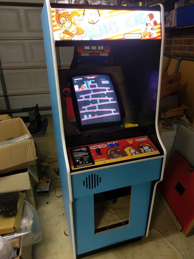
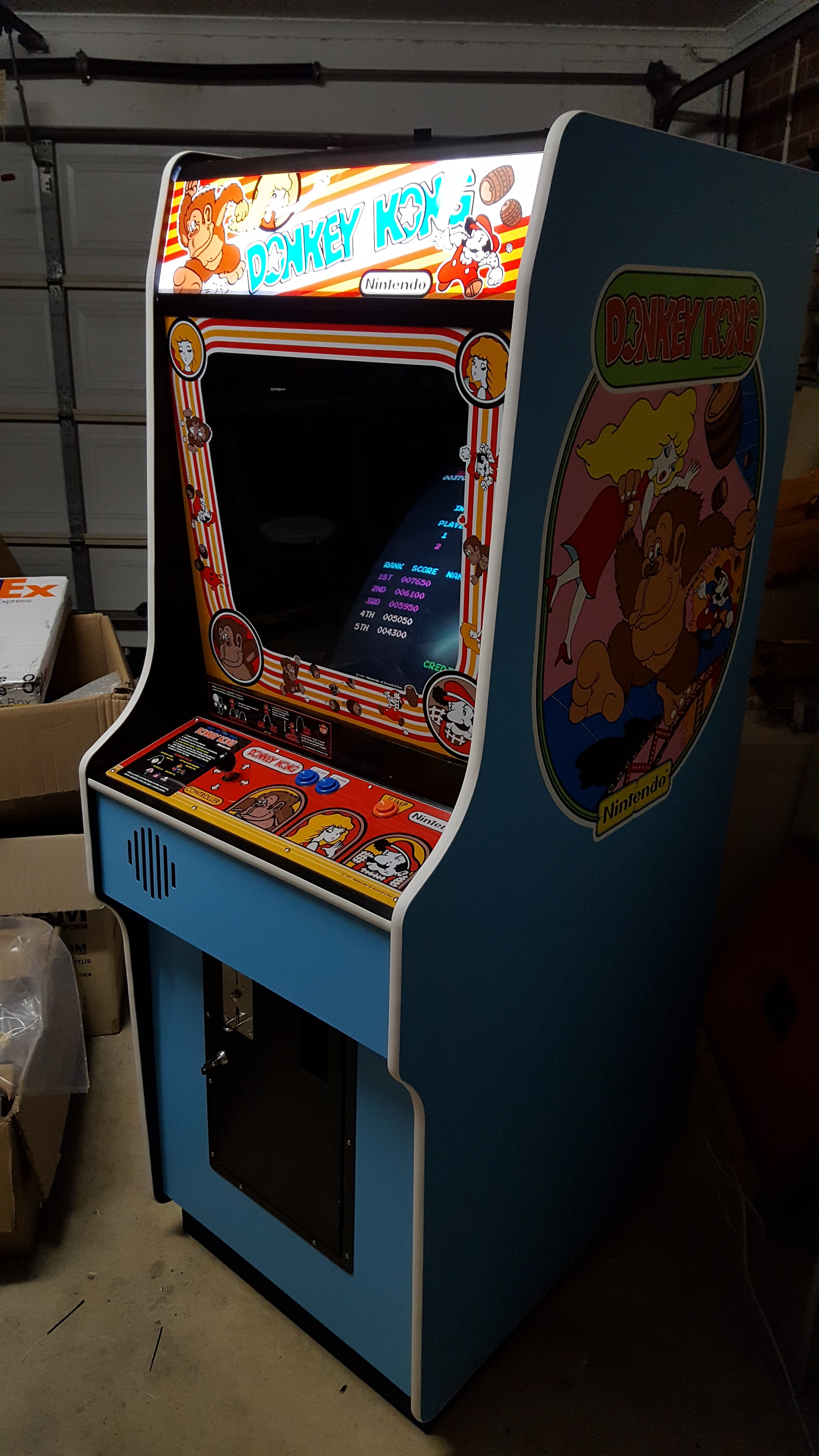
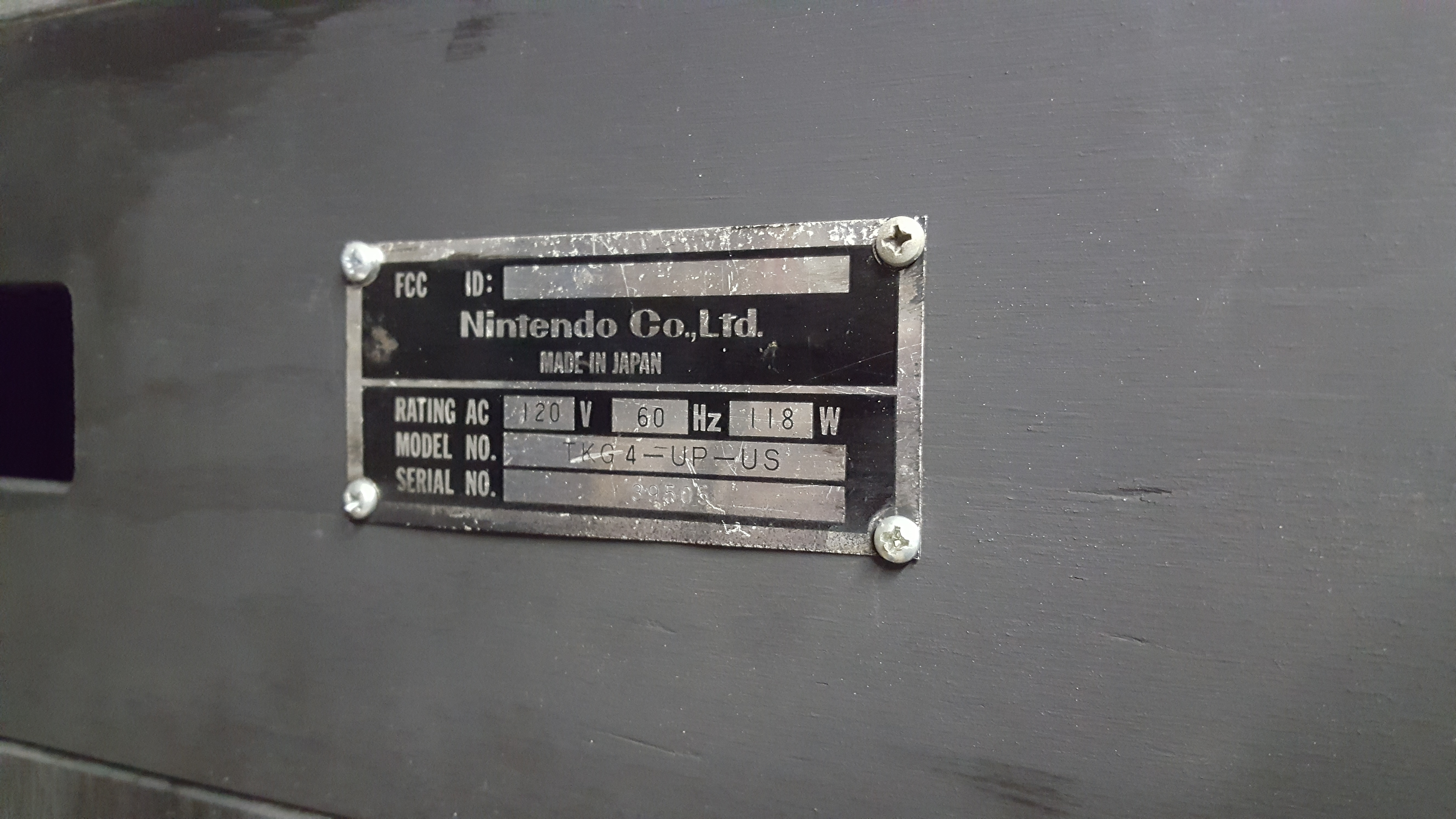
All in all I was very happy with how this turned out. Without looking on the inside of the cab I would challenge anyone to pick the difference between this and an original cab. All of the reproduction parts from Mikes Arcade fitted perfectly so I am pretty confident that the measurements for this cab are spot on. As for a finishing touch I even added an original Nintendo serial plate for this cab on the back!

Now for the next project!